Connecting machine to power source, Electrical connections single phase installation – Delta 50-851 User Manual
Page 10
10
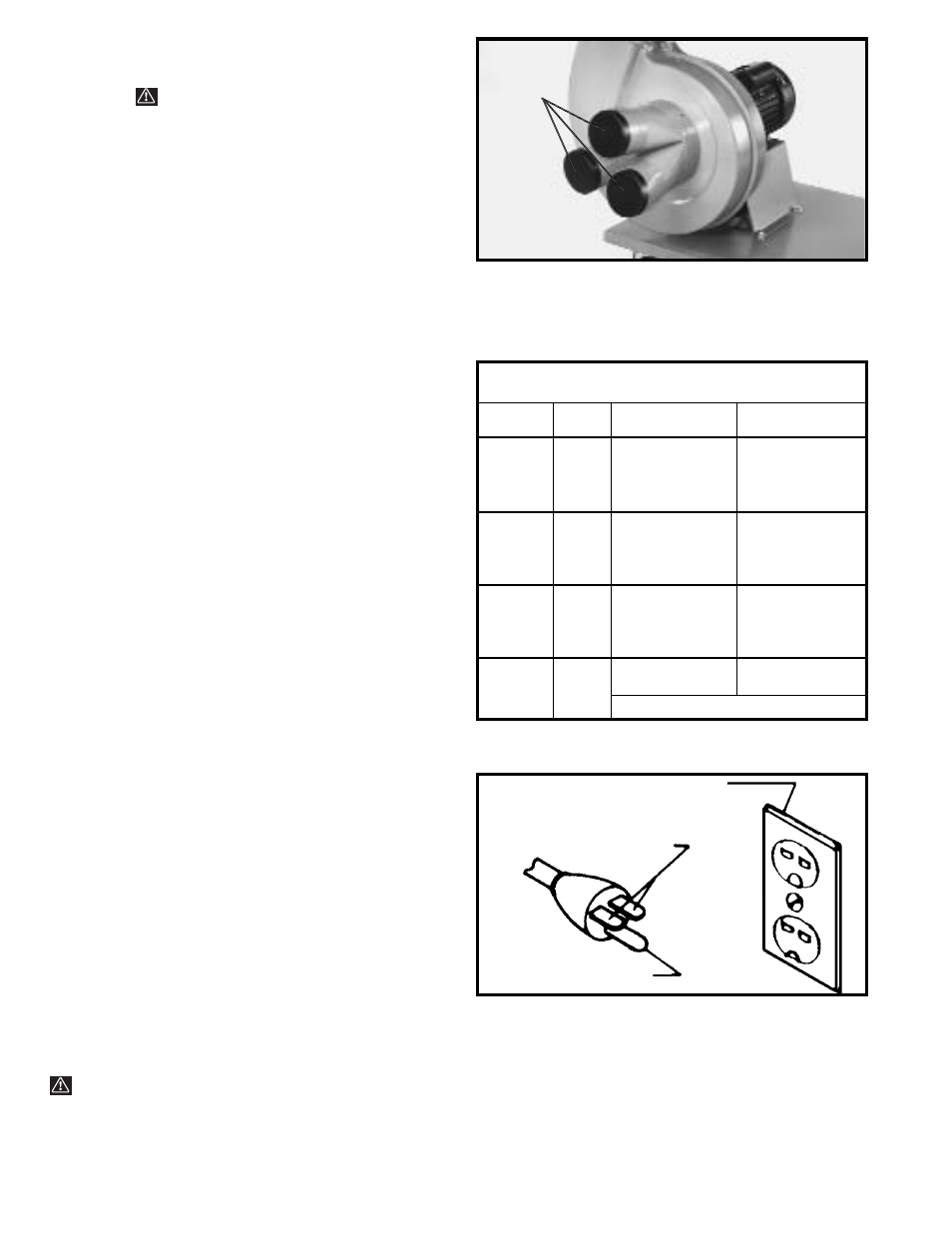
Fig. 25
3.
Three dust intake port caps (D) Fig. 25, are supplied
with the dust collector. NOTE: These caps should be
inserted into the intake ports as shown, when they are
not in use.
WARNING: DO NOT INSERT FINGERS
OR ANY FOREIGN OBJECT INTO THE DUST INTAKE
PORTS WHEN UNIT IS OPERATING.
CONNECTING MACHINE TO POWER SOURCE
ELECTRICAL CONNECTIONS
SINGLE PHASE
INSTALLATION
The motor rating of the Model 50-851 Dust Collector is
2 HP, 230 Volt, Single Phase. Before connecting your
dust collector to an electrical power system, be sure the
electrical system agrees with the motor rating of the
tool.
The power cord is equipped with a plug that has two flat,
current-carrying prongs in tandem and one round or “U”
shaped, longer ground prong. This is used only with the
proper mating 3-conductor grounding type receptacle
as shown in Fig. 26.
When the 230 Volt three-prong plug on your machine is
plugged into a grounded 3-conductor receptacle, the long
ground prong on the plug contacts first so the machine
is properly grounded before electricity reaches it.
WARNING: MAKE CERTAIN THE RECEPTACLE IN
QUESTION IS PROPERLY GROUNDED. IF YOU ARE
NOT SURE, HAVE A QUALIFIED ELECTRICIAN CHECK
THE RECEPTACLE.
Fig. 26
CURRENT CARRYING
PRONGS
GROUNDED OUTLET BOX
GROUND PRONG
D
A separate electrical circuit should be used for your
tools. This circuit should not be less than #12 wire and
should be protected with a 20 amp time lag fuse. Use
proper extension cords. Make sure your extension cord
is in good condition and is a 3-wire extension cord
which has a 3-prong grounding type plug and a 3-hole
receptacle which will accept the tool’s plug. When using
an extension cord, be sure to use one heavy enough to
carry the current of the tool. An undersized cord will
cause a drop in line voltage, resulting in loss of power
and overheating. Fig. 25A, shows the correct gauge to
use depending on the cord length. If in doubt, use the
next heavier gauge. The smaller the gauge number, the
heavier the cord. Have a certified electrician repair or
replace damaged or worn cord immediately. Before
connecting the motor to the power line, make certain the
switch is in the “OFF” position and be sure that the
electric current is of the same characteristics as
stamped on the motor nameplate. All line connections
should make good contact. Running on low voltage will
damage the motor.
Fig. 25A
MINIMUM GAUGE EXTENSION CORD
RECOMMENDED SIZES FOR USE WITH STATIONARY ELECTRIC TOOLS
Ampere
Total Length
Gauge of
Rating
Volts
of Cord in Feet
Extension Cord
0-6
240
up to 50
18 AWG
0-6
240
50-100
16 AWG
0-6
240
100-200
16 AWG
0-6
240
200-300
14 AWG
6-10
240
up to 50
18 AWG
6-10
240
50-100
16 AWG
6-10
240
100-200
14 AWG
6-10
240
200-300
12 AWG
10-12
240
up to 50
16 AWG
10-12
240
50-100
16 AWG
10-12
240
100-200
14 AWG
10-12
240
200-300
12 AWG
12-16
240
up to 50
14 AWG
12-16
240
50-100
12 AWG
12-16
240
GREATER THAN 100 FEET NOT RECOMMENDED