Motherboard internal diagram, Rear io (please refer to page3) – Jetway Computer NF9U User Manual
Page 9
4
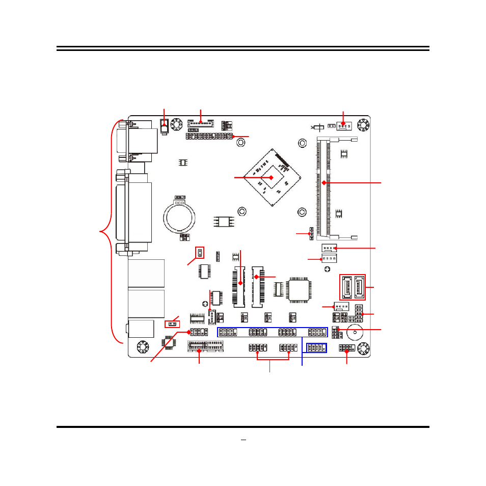
Motherboard Internal Diagram
Note: 1.The module for SODIMM1 should be DDR3L 1.35V SODIMM and not exceeding 8GB total
capacity. 2. The SODIMM installed should be of or above the memory clock the model supported,
otherwise the board will not start. 3. MSATA slot shares function with SATA2 port; i.e. only one can
function at a time.
9V~24V Internal
Power Connector
Intel CPU
PCI Express x1 Slot
Front Panel
Audio Header
Front Panel Header
LVDS Inverter
Serial Port Headers
(COM
2
/3/4/5/6)
GPIO Header
SATA Hard Disk
Power-Out Connector
Speaker
Connector
LVDS Header
SATAII Ports
SYSFAN1 Header
LAN_LED1 Header
*DDR3L SODIMM Slot
(SODIMM1)
Power LED Header &
Speaker Header
Half-size Mini-PCIE
Slot (MPE1)
Full-size M-SATA
Slot (MSATA1)
*Rear IO
(Please
refer to
Page3)
CPUFAN Header
SMBUS Header
LAN1_LED1
Header
LAN2_LED1
Header
SYSFAN2 Header
USB 2.0 Headers