53sa-7 – James Loudspeaker 53SA-7 User Manual
Page 2
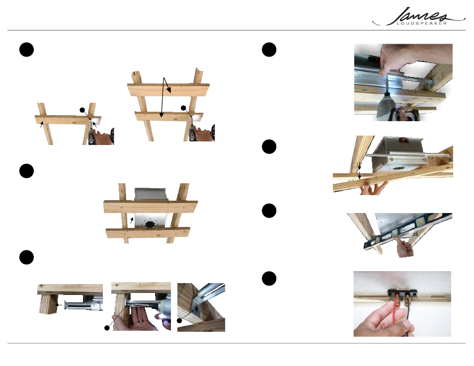
4
Place the speaker on top of the
the temporary holders
Page 3
5
Expand the bracket to fit from joist to joist (Fig. 8). Then fix to the joists using
a drywall screw (Fig. 9). Make certain the bracket is flush with the joist (Fig.10).
(Drywall screws not included).
Fix the brackets to the Joists
3
Cut a couple a 2 x 4s or 1 x 2s, a
few inches wider than the ceiling
joists. Then with a couple of drywall
screws, mount the temporary
holders to the joists. (Drywall screws
not included).
Mount temporary holders to joists
These will help you
hold the speaker up
and make the speaker
mount flush to the
future drywall.
Fig. 5
Fig. 6
Fig. 7
Fig. 8
Fig. 9
Fig. 10
H
Installation guide for the 53SA-7 In-Ceiling Speaker
53SA-7
7
Remove the temporary
holders from the joists
8
Double check that the
face of the speaker
is plumb with joist
Adjust if needed
(loosen the bracket
slightly and adjust the
speaker’s position up
or down or as required
(Fig. 13).
Tighten screws enough
to securely fix the
bracket to the speaker
case. Be careful not to
strip the threads on the
brackets (Fig. 11).
You can adjust the side-
to-side position of the
speaker by sliding the
bracket before
tightening.
6
Firmly secure the bracket
to the speaker
Remove drywall
screws and remove the
temporary holders
(Fig. 12).
Fig. 11
Fig. 12
Fig. 13
Page 2
9
Strip and insert wires
into terminals
Minimum 18 gauge wire,
heavier gauges for longer
wire runs.
H
H
H
Fig. 14
Note: 63SA-7 is pictured in
steps 2,4,7. Procedures for
53SA-7 are identical.