Operating adjustments, Setting the table for horizontal or bevel cutting, Aligning the degree scale pointer – Dremel 1680 User Manual
Page 10
NOTE: When cutting at extreme angles, the drop foot
should be lifted off the workpiece, as it will impede cutting.
Hold the workpiece against the table. The drop foot may
be disassembled when thick materials are cut at extreme
angles.
10.
Operating Adjustments
Setting the Table for
Horizontal or Bevel Cutting
1. Loosen the table lock knob, and the saw table can be
tilted to the right or left and locked at any angle from 0
degree horizontal cutting position up to 45 degrees for
bevel cutting (Fig. 4). Your tool also features table tilt den-
tents which automaticlly stops the table to the right or left
every 15 degrees.
2. A degree scale is also provided under the work table as
a convenient reference for setting the approximate table
angle for bevel cutting. When greater precision is required,
make practice cuts and adjust the table as necessary for
your requirements.
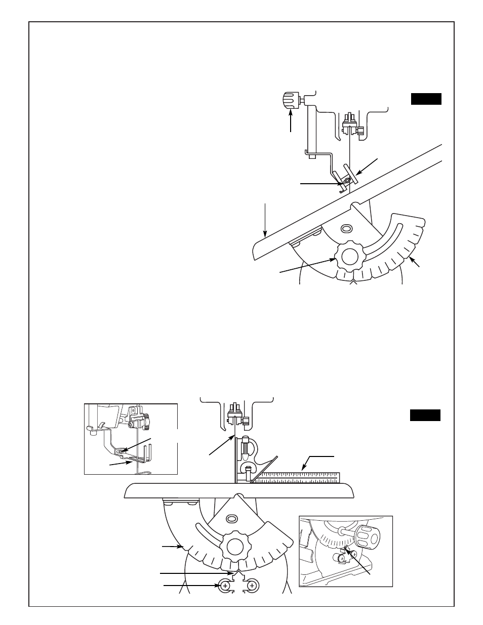
Adjusting the hold down clamp
The hold down clamp should always rest just above the
workpiece to help prevent the workpiece from lifting from
the table.
1. Hold the drop foot, loosen the drop foot lock knob and
lower by hand until it just rests above the workpiece sur-
face, and securely tighten the drop foot lock knob.
2. When cutting with the table angled, adjust drop foot so
it’s parallel to the table. To adjust, loosen screw with the
allen wrench provided, turn foot to correct angle, tighten
screw.
Always make sure the blade does not contact either side
of the drop foot, or the table opening.
TABLE
TABLE
LOCK KNOB
SQUARE
BLADE
DEGREE
SCALE
POINTER
POINTER
ADJUSTMENT SCREW
FIG. 5
FIG. 4
DROP
FOOT
DROP
FOOT
LOCK
KNOB
DEGREE
SCALE
Aligning the Degree Scale Pointer
STEEL
BALL
DROP
FOOT
MOUNTING
SCREW
The table is factory set to 0º. If further adjustments are
necessary, please follow the instructions below:
1. Loosen the table lock knob and move the table until it is
90 degree to the blade.
2. With the wrench provided remove the drop foot assem-
bly, mounting screw, and washer, and move it out of the
way. Place a small square on the table next to the blade as
shown in (Fig. 5) to check if the table is 90º to the blade. If
no adjustment is required, replace the drop foot assembly,
washer and screw.
If adjustment is necessary. Loosen, but don’t remove the
two screws holding the pointer. With the steel ball cen-
tered in the 0º detent, slide the pointer left or right until the
blade is parrallel to the square.
4. Tighten the table lock knob, both screws, and replace
drop foot, washers and screw. Remember, the degree
scale is a convenient guide but should not be relied upon
for precision. Make practice cuts in scrap wood to deter-
mine if your angle setting is correct.
MOUNTING
SCREW