IBASE ET860 User Manual
Page 15
INSTALLATIONS
ET860 User’s Manual
9
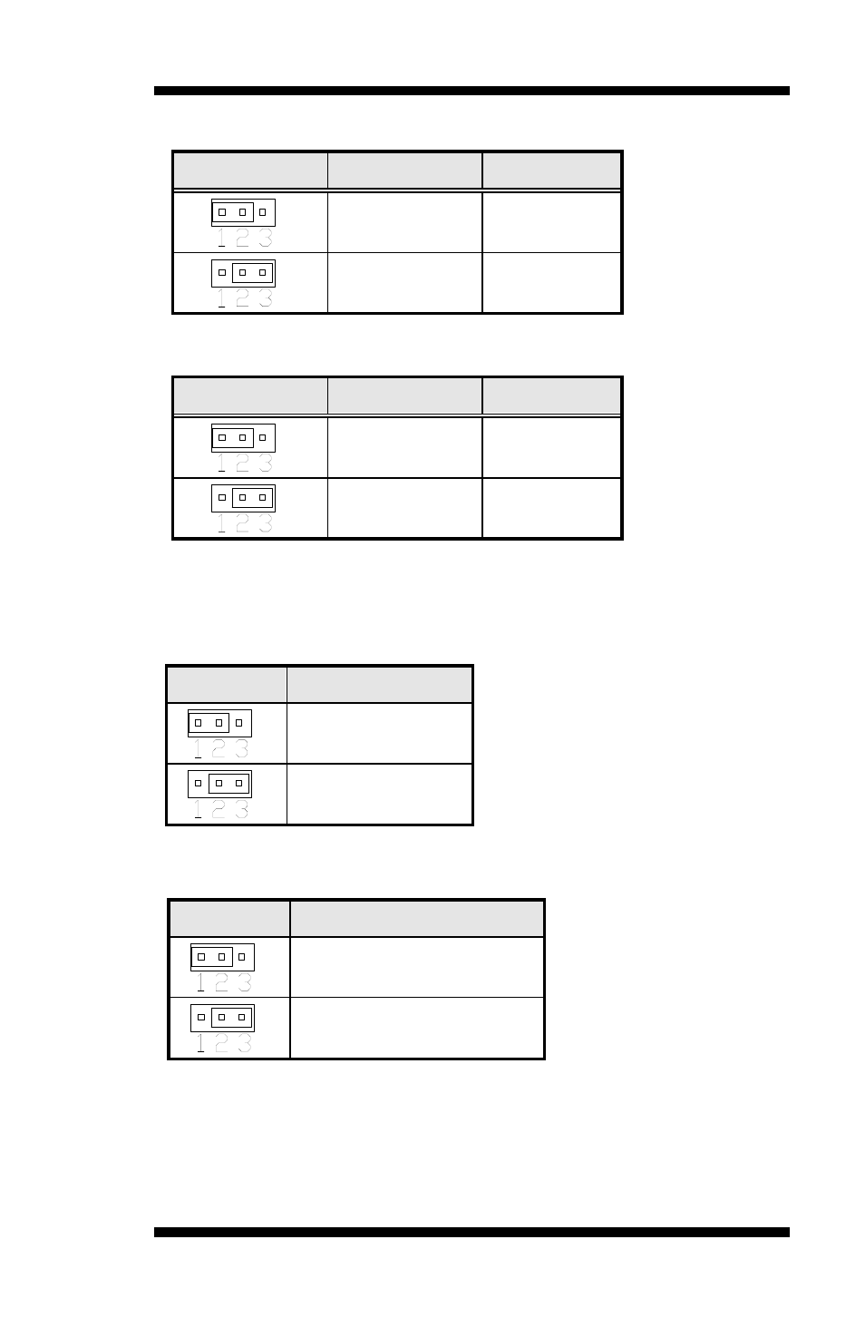
JP1: Clear CMOS Contents
JP1
Setting
Function
Pin 1-2
Short/Closed
Normal
Pin 2-3
Short/Closed
Clear CMOS
JP2: Clear SRTC Register Contents
JP2
Setting
Function
Pin 1-2
Short/Closed
Normal
Pin 2-3
Short/Closed
Clear
[
JP3: SPI Flash connector (Factory use only)
JP4: Micro SD Power
JP5: DVI or LVDS down to carrier board
Note: JP5 supports ET860-I27 (w/o LVDS)
module
only.
CN1: Micro SD Connector
JP4
Micro SD Power
+3.3V (default)
+1.8V
JP5
DVI or LVDS Selection
DVI (default)
LVDS