IBASE IB908 User Manual
Page 23
INSTALLATIONS
IB908F User’s Manual
19
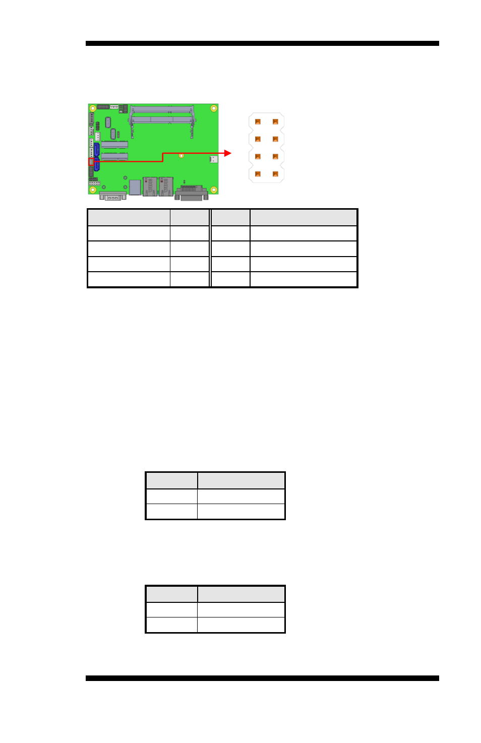
J14: Front Panel Connector
The following table shows the pin outs of the 2x4 pin header
Signal Name
Pin # Pin #
Signal Name
Ground
1
2
PWR_SW
PWR_LED+
3
4
PWR_LED-
HDD_LED+
5
6
HDD_LED-
Ground
7
8
RESET
J14 provides connectors for system indicators that provide light
indication of the computer activities and switches to change the computer
status.
J14 is an 8-pin header that provides interfaces for the following
functions.
ATX Power ON Switch: Pins 1 and 2
This 2-pin connector is an “ATX Power Supply On/Off
Switch” on the system that connects to the power switch on
the case. When pressed, the power switch will force the
system to power on. When pressed again, it will force the
system to power off.
Power LED: Pins 3 and 4
Pin #
Signal Name
3
LED(+)
4
LED(-)
Hard Disk Drive LED Connector: Pins 5 and 6
This connector connects to the hard drive activity LED on
control panel. This LED will flash when the HDD is being
accessed.
Pin #
Signal Name
5
LED(+)
6
LED(-)
1
7
2
8