IBASE MI802 User Manual
Page 21
INSTALLATIONS
MI802 User’s Manual
17
LVDS Connectors: 2X10_1.25mm_Straight_Male_DF13 (Hirose
DF13-20DP-1.25V)
The LVDS (24bit) connectors on board consist of the first channel
(LVDS1) and second channel (LVDS2).
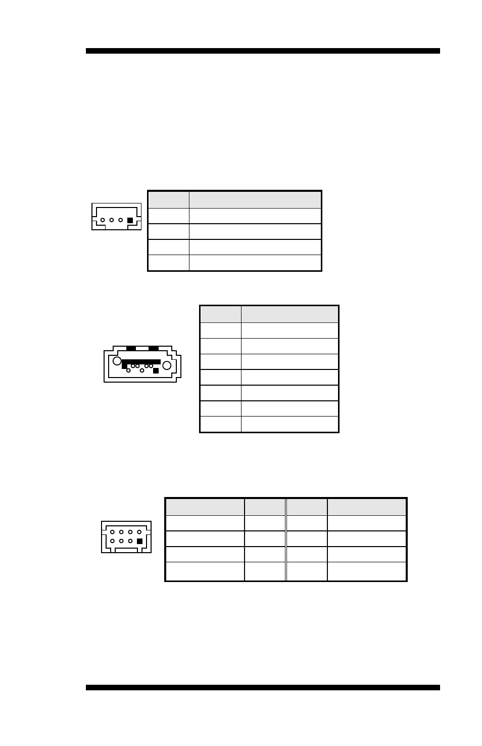
CN13: LCD Backlight Connector
1X4_2.0mm_Straight_M(JST B4B-PH-K-S)
4
1
Pin #
Signal Name
1
+3.3V/5V/12V*
2
Backlight Enable
3
Brightness Control
4
Ground
CN14,CN16: SATA Connectors
1
7 4
Pin #
Signal Name
1
Ground
2
TX+
3
TX-
4
Ground
5
RX-
6
RX+
7
Ground
CN17: USB6/7 Ports Header
2X4_2.0mm_Straight_Male_DF11 (Haoguo DF11-8S-PA66H, Mating
connector: Hirose DF11-8DS-2C or compatible)
1
7
2
8
Signal Name
Pin #
Pin #
Signal Name
+5V
1
2
Ground
Data-
3
4
Data+
Data+
5
6
Data-
Ground
7
8
+5V
CN18: iSMART JTAG Pin Header (factory use only)
CN20, CN21: Mini PCIE Connector
Remarks: CN20 USB signal is shared with J5.