IBASE MI802 User Manual
Page 12
INSTALLATIONS
8
MI802 User’s Manual
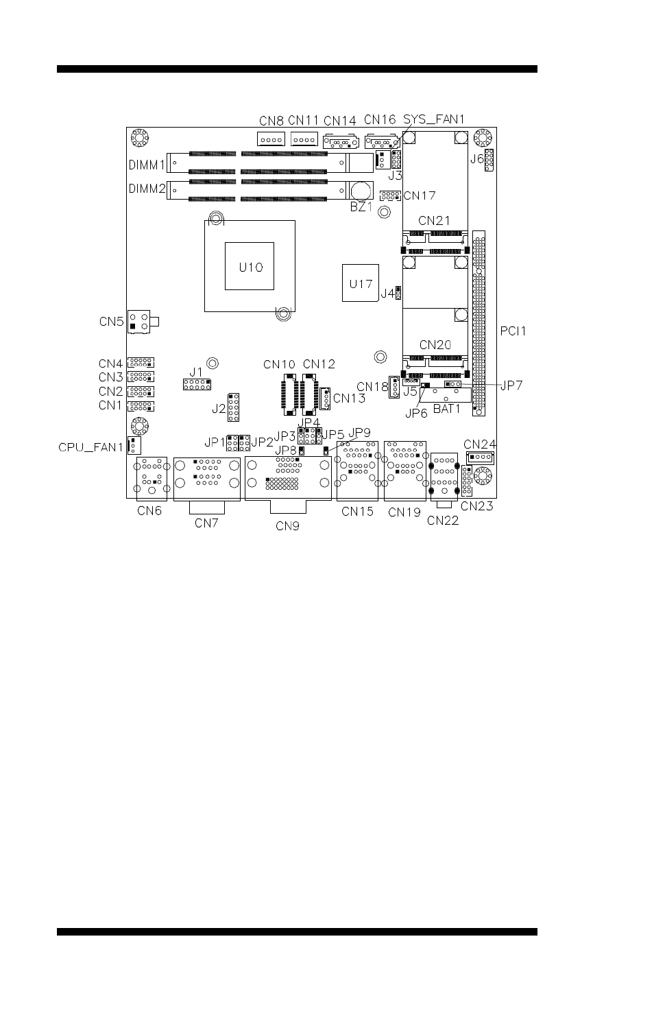
Jumper Locations on MI802
Jumper Locations on MI802 ........................................................... Page
JP1: COM1 RS232 RI/+5V/+12V Power Setting ................................. 9
JP2: COM2 RS232 RI/+5V/+12V Power Setting ................................. 9
JP3: LCD Panel Power Selection ......................................................... 9
JP4: LCD Backlight Power Selection ................................................... 9
JP5: LCD BackLight Control Selection .............................................. 10
JP7: Clear CMOS Setting .................................................................. 10
JP8: LCD BackLight Control Output Level ....................................... 10
JP9: LCD Boot ROM Protect (factory use only) ................................ 10
SW1: Panel Type Selection ................................................................ 10