Herrmidifier Herrtronic MD Engineering Guide User Manual
Page 5
Herrtronic
®
MD Series
E n g i n e e r i n g G u i d e
5
www.herrmidifier-hvac.com
CONTROL MODE
SETPOINT
PARAMETERS
ON/OFF
PROP.
PROP.
INT
PASS-
WORD
SECURED
Steam Rating
(1,2)
(Lbs/Hr)
Electrode Rating
(1,3)
(Amps)
Capacity Setpoint
(1)
(% Cap.)
Lo Drain Threshold
(1)
(% Cap.)
Hi Drain Threshold
(% Cap.)
Auto Drain
(1)
(Days)
Manual Drain
(1)
(Active/Inactive)
Drain Tempering
(Active/Inactive)
Control Setpoint
(1,4)
(% R.H.)
Limit Setpoint
(1,5)
(% R.H.)
Hi Humidity Alarm
(% R.H.)
Lo Humidity Alarm
(% R.H.)
Cycle Time
(Secs.)
Proportioning Band
(% R.H.)
Integration Period
(Mins.)
Throtting Range
(% R.H.)
Unit Address
(Unit #)
Leakage Protection
(1)
(On/Off)
Electrode Run
(1)
Time (Hrs.)
Limit Input
(Enabled/Disabled)
Control Input
(Enabled/Disabled)
Notes:
1. Certain “Setpoint Parameters” are presented in “Display Mode”.
2. “Steam Output” in display mode.
3. “Electrode Current” in display mode.
4. “Control Humidity” in display mode.
5. “Limit Humidity” in display mode.
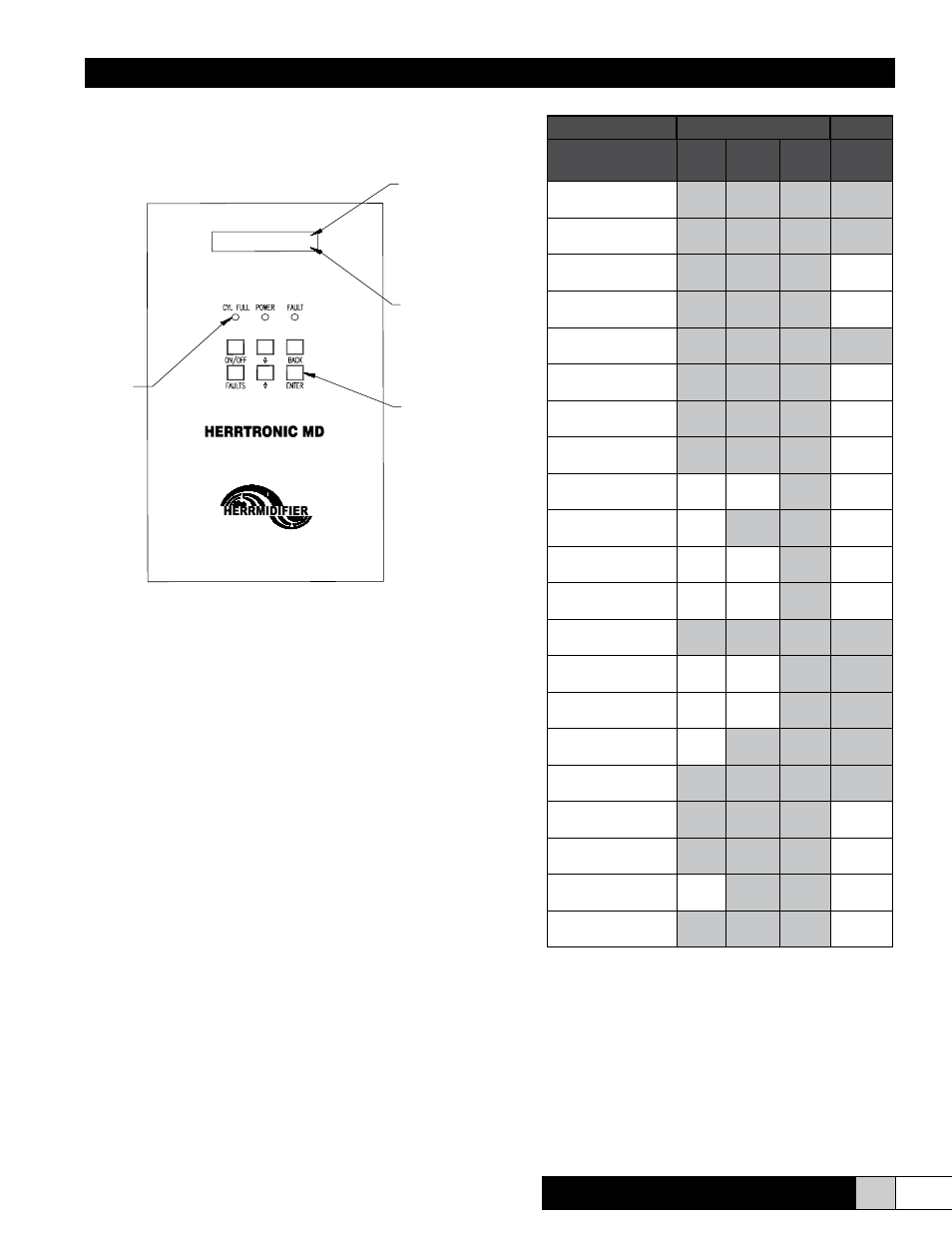
LED Indicators
* Cyclinder Full
* Power On
* Fault
LCD Display
Line 1:
* System On/Off
* Output Capacity
* Control Type
* Unit Address
Line 2:
* System Parameters or
Setpoint Adjustment
* Fault indicator
Keyboard
* Enter each menu (5 total)
* Scroll thru parameters or
Set points
* Adjust setpoints
* Enter password as needed
* Identify “fault” causes
Herrtronic MD - Features at Your Fingertips