Herrtronic md general applications, Herrtronic, Md series – Herrmidifier Herrtronic MD Engineering Guide User Manual
Page 10
Herrtronic
®
MD Series
E n g i n e e r i n g G u i d e
10
www.herrmidifier-hvac.com
Herrtronic MD General Applications
Engineering and Application
Herrtronic MD Series Steam Humidifiers can be applied in a variety of
applications. The simplest application consists of an “MD” unit and an
“RDU” (Room Distribution Unit). Steam is generated by the “MD” unit,
flows to the “RDU” unit, and is distributed in to the conditioned space.
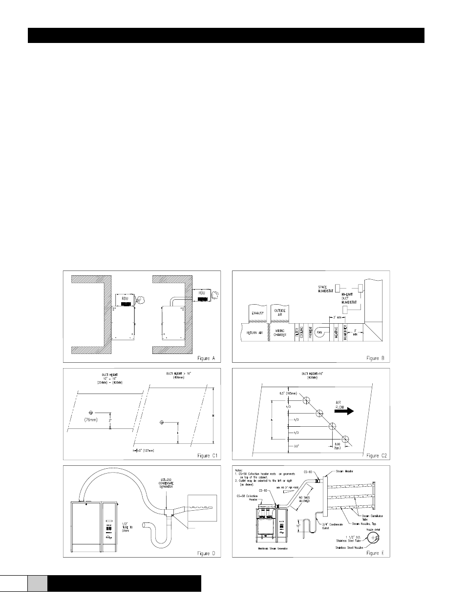
As shown in Figure A, the “RDU” unit can be mounted on the MDS or
MDD units or remote mounted with any “MD” configuration. Steam input
is either into the bottom or rear of the “RDU” unit. In this application, only
the “RDU” needs to be in the conditioned space. One “RDU” is required
per “MDM” or “MDS” unit. Two “RDU” units are required for each “MDD”
unit.
Note: a condensate return line (provided) must be installed between the
“RDU” and “MD” units in the field.
Alternatively, steam generated by an “MD” unit can be discharged
directly into the system ductwork. In this application, steam distributor
pipe(s) are installed in the system ductwork with laminar airflow with
at least three (3) feet downstream clearance. Actual requirements
depend on your exact psychrometric conditions. Consult factory if you
should have any questions. If the blower operates intermittently, an air-
proving switch should be installed to insure blower operation prior to the
humidifier turning “on.” A high limit humidistat or sensor, located at least
10’ downstream of steam distributor, should be included for better system
control.
The number of steam outlets on the humidifier is as follows:
MDM – 1 outlet
MDS up to 50 lbs/hr. – 1 outlet
MDS up to 100 lbs/hr. – 2 outlets
MDD – 4 outlets.
A CS-58 Dual Outlet Adapter is available to convert to two (2) 1 ½” outlets
to a single 2” hose connection. Figures C1 and C2 reflect the spacing
required within the duct. Note: the standard steam distributors are sloped
to return condensate to the humidifier.
The steam piping from the humidifier to the steam distributor should have
a slope of +8% up to the steam distributor. Steam hose may be used to
a maximum of 20’ between the humidifier and the distributor. Beyond 20’,
system capacity is significantly reduced unless insulated copper pipe,
1-1/2 or 2” ID, is used. If there are any low spots between the humidifier
and the distributor, a condensate separator (such as EST-250) should
be used (Figure D). MDS and MDD system are designed for a maximum
of 7” duct static pressure. MDM units are designed for a maximum of 5”
duct static pressure. Consult the factory if you exceed these levels.
For applications requiring a short, guaranteed absorption distance,
consult the factory for selection of the appropriate CS Series steam
distribution system (Figure E).
AT LOWEST
POINT