Gullco GK-200-RLx-I User Manual
Page 15
13
the faceplate of the controls. Other styles of control are available where the removal of a hole-plug
for access and a small flat-bladed screwdriver for adjustment are required (as shown in adjacent
sketch).
Zero (0) (top dead center) is the normal operating location for the rotary selector switch. When in
any position other than zero (0) the control is in programming mode, the round, Auto Cycle Mode
L.E.D. in the bottom right hand corner of the display will flash and the motor control will not allow
normal operation.
To make changes to the program variables, turn the power on and place the Run/Stop switch in the
Stop position, then rotate the Program Variable Selector switch to the variable (parameter) to be
altered (the Auto Cycle Mode L.E.D. will flash on and off). The number of the variable parameter
will be displayed when the Forward/Neutral/Reverse switch is in the Neutral position. I.e. Cycle
Control (Master) - “P. 1”, “P. 2”, “P. 3”, etc. & Index Control (Slave) - “P.I.1”, “P.I.2”, “P.I.3”, etc. To
see the current value/setting of the variable, place the Forward/Neutral/Reverse switch in either the
Forward or Reverse position. To increment the value/setting, place the Forward/Neutral/Reverse
switch in the Forward position and press the Cycle Push Button. To decrement the value/setting,
place the Forward/Neutral/Reverse switch in the Reverse position and press the Cycle Push Button.
Pressing the Cycle Push Button briefly will increment/decrement the value/setting by one, whereas
keeping the Cycle Push Button depressed will scroll through the values/settings until released. The
speed display and/or the individual L.E.D.’s will indicate the chosen value/setting. When all of the
program variables are set, place the Program Variable Selector switch back to the zero position (the
Auto Cycle Mode L.E.D. will stop flashing).
The values/settings of the variables are stored on the product/application specific micro-processor
chip. If the chip is replaced, the values/settings of the variables will need to be re-entered.
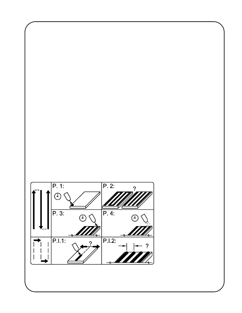
The following label is applied to each “KAT”
®
carriage indexing system to graphically identify the
individual programmable parameters/variables:
P. 1 = Travel Motion Delay
P. 2 = Arc On/Off During Index
P. 3 = Crater Fill Delay
P. 4 = Post Weld Delay
P.I.1 = Index Direction
P.I.2 = Index Distance