Valve design and function – Groth 1720A User Manual
Page 3
3
VALVE DESIGN AND FUNCTION:
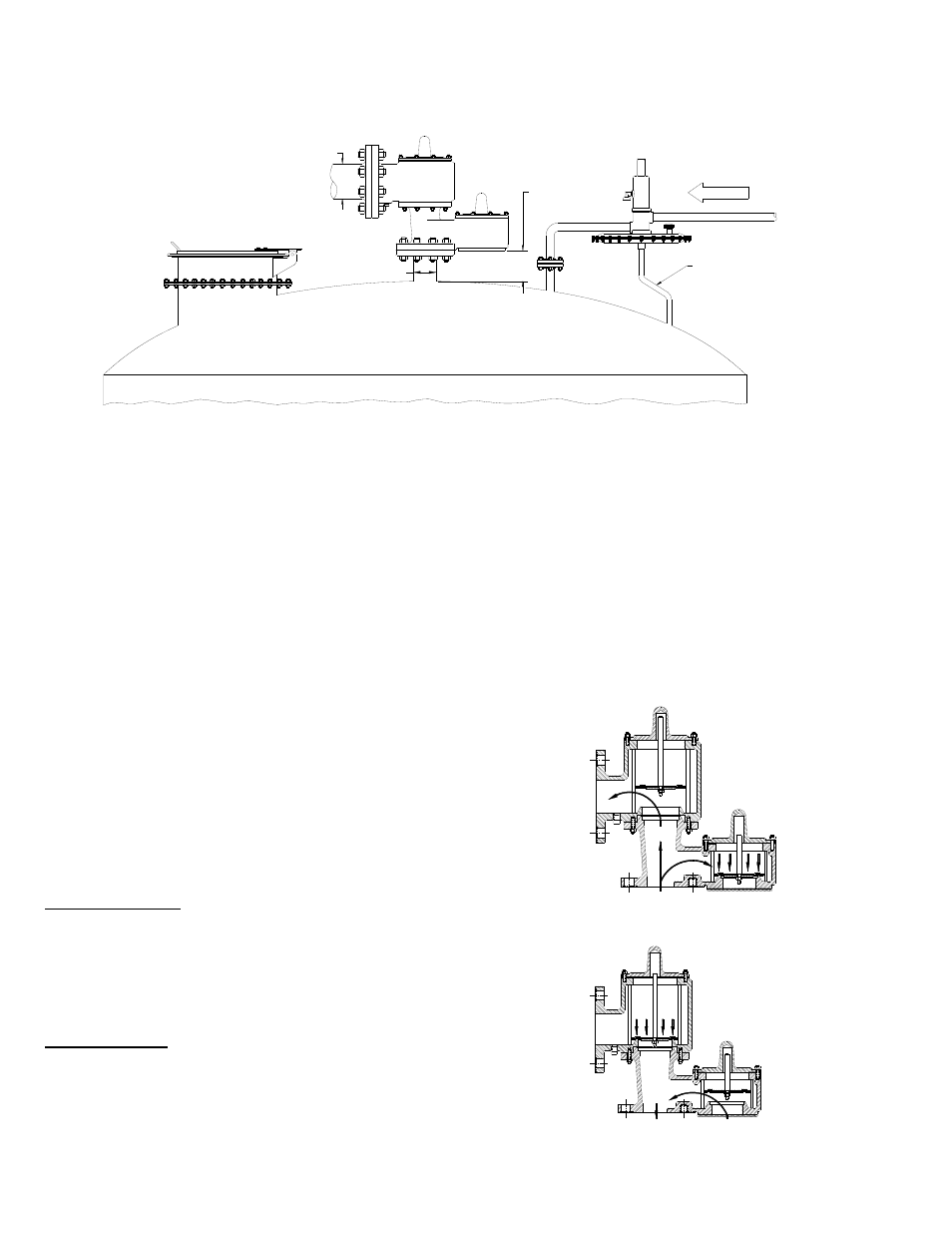
Fig. 1 - Typical Tank Installation
Tank protection equipment typically includes
an operating valve which is designed to
provide pressure/vacuum relief under normal
pump in/out and thermal breathing conditions.
An emergency relief valve can also provide
both pressure and vacuum relief and normally
it is sized to provide pressure relief if there is
a fire in the immediate vicinity of the tank. It
may also be sized by the tank designer to
provide protection in the event of equipment
failure (such as the rupture of a process
steam line or an inert gas blanketing system
failing “wide open”) or operator error.
A typical tank installation is shown in Fig. 1
which includes the following Groth products:
Model 1720A ‘P/V’ Weight Loaded Valve
Model 3000 Gas Blanketing Regulator
Model 2400 Emergency ‘P’ Relief Valve
Pressure Relief: As the pressure in the
storage tank increases, the vacuum pallet is
held shut. When the set pressure is reached,
the pressure pallet lifts and relieves to
atmosphere (or to a header if it is a pipe away
valve). See Fig. 2.
Vacuum Relief: As a vacuum is drawn in the
storage tank (for example, when fluid is being
pumped out), the pressure pallet is held shut
by atmospheric pressure. When the vacuum
setting is reached, the pallet lifts and air is
drawn in from the atmosphere. See Fig. 3.
Installation Notes: (See Fig. 1 above)
1. Minimum clearance between tank roof and
vacuum inlet port must be at least equal to
the valves’ nominal flange bore.
2. Tank nozzle bore must be > or = valve
inlet flange bore.
3. Inlet and outlet piping loads must be
supported by appropriate structural
supports, NOT by the valve body.
Fig. 2- Pressure Relief
Fig. 3 - Vacuum Relief
RELIEF VALVE
PRESSURE/VACUUM
EMERGENCY RELIEF VALVE
SEE NOTE 2
SEE NOTE 3
1720A
TUBING
FLOW
BLANKET GAS REGULATOR
SEE NOTE 1