Operators safety summary, 180 mhz – FSR YUV-6 User Manual
Page 2
PROPRIET
ARY INFORMA
TION
All information in this manual is pr
oprietary to and the
p
roperty of FSR inc. This publication is pr
otected by the Federal
Copyright Law
, with all rights r
eserved. No par
t
of this document may be r
epr
oduced, transcribed, or transmitted,
in any form or by any means, without prior
explicit written permission fr
om FSR inc.
Operators Safety Summary
The general safety information in this summary is for operating
personnel.
Do Not Remove Covers or Panels
There are no user-serviceable
parts within the unit. Removal of the top cover will expose
dangerous voltages.
T
o
avoid personal injury
, do not remove the
top cover
. Do not operate the unit without the cover installed.
Power
Sour
ce
This product is intended to operate from a power
source that will not apply more than 230 volts rms between the
supply conductors or between both supply conductor and ground.
A protective ground connection by way of grounding conductor in
the power cord is essential for safe operation.
Gr
ounding the Product
This product is grounded through the
grounding conductor of the power cord.
T
o
avoid electrical shock,
plug the power cord into a properly wired receptacle before
connecting to the product input or output terminals. A protective-
ground connection by way of the grounding conductor in the power
cord is essential for safe operation.
Use the Pr
oper Power
Cord
Use only the power cord and
connector specified for your product. Use only a power cord that is
in good condition. Refer cord and connector changes to qualified
service personnel.
Use the Pr
oper
Fuse
T
o
avoid fire hazard, use only the fuse having
identical type, voltage rating, and current rating characteristics.
Refer fuse replacement to qualified service personnel.
Do Not Operate in Explosive
Atmospher
es
T
o
avoid explosion,
do not operate this product in an explosive atmosphere.
Output Impedance:
75
Ohms
Propagation Delay:
15 nS max
Rise/Fall Time:
1
nS
Digital Audio Input
Number/T
ype:
1 Dolby Digital, DTS, AES/EBU, SP/DIF
Connectors:
1 female BNC
Impedance:
510 Ohms
Nominal Level: 1V (consumer), 2V (professional)
Mim/Max Levels: 0.5V p-p to 5V p-p
Sampling Rates: 32 kHz, 44.1 kHz, 48 kHz, 96 kHz
Digital Audio Output
Number/T
ype:
6 Dolby Digital, DTS, AES/EBU, SP/DIF
Connectors:
6 female BNC
Impedance:
75 Ohms
Output Level:
2.4V p-p into 75 Ohms
Propagation Delay: 15 nS max
Rise Fall T
ime: 1 nS max
General
Power:
100V
AC to 240V
AC, 50/60 Hz, internal, autoswitch
0.65A/1
1
5
V
, 0.4A/230V
Enclosure:
Metal 1 Rack Unit
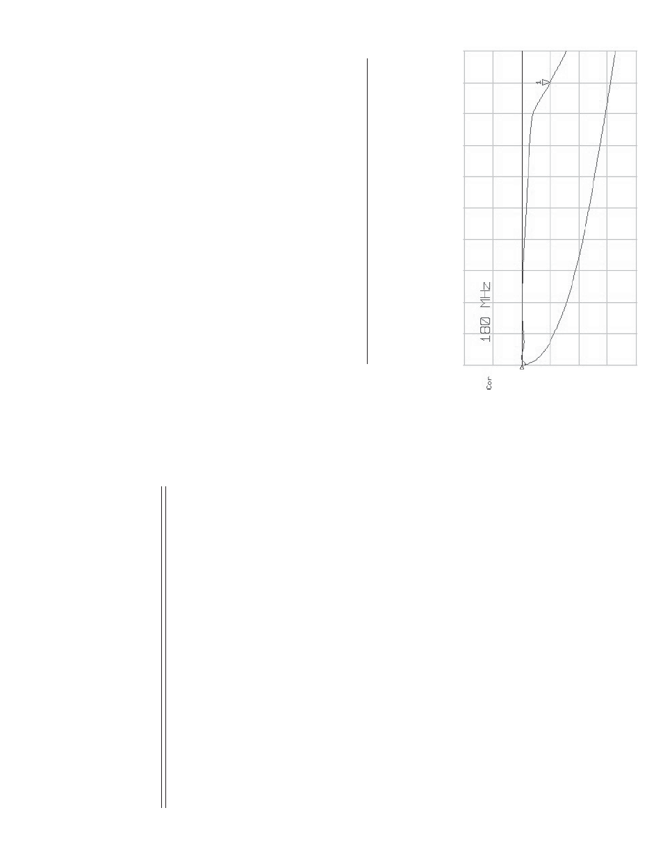
Graph
A
shows the response curves of a 150 foot section of West Penn
8255 mini-coax cable with and without the YUV-6 being driven by a
full .7V signal. Notice that by it
self, the cable’s -3dB bandwid
th is only
17 MHz, but when used with the RGB-4/6, the bandwidth is restored to
180 MHz at the end of the150 foot cable.
180 MHz