Mounting detail typical installation, Front view rear view – FSR CI-5UT User Manual
Page 4
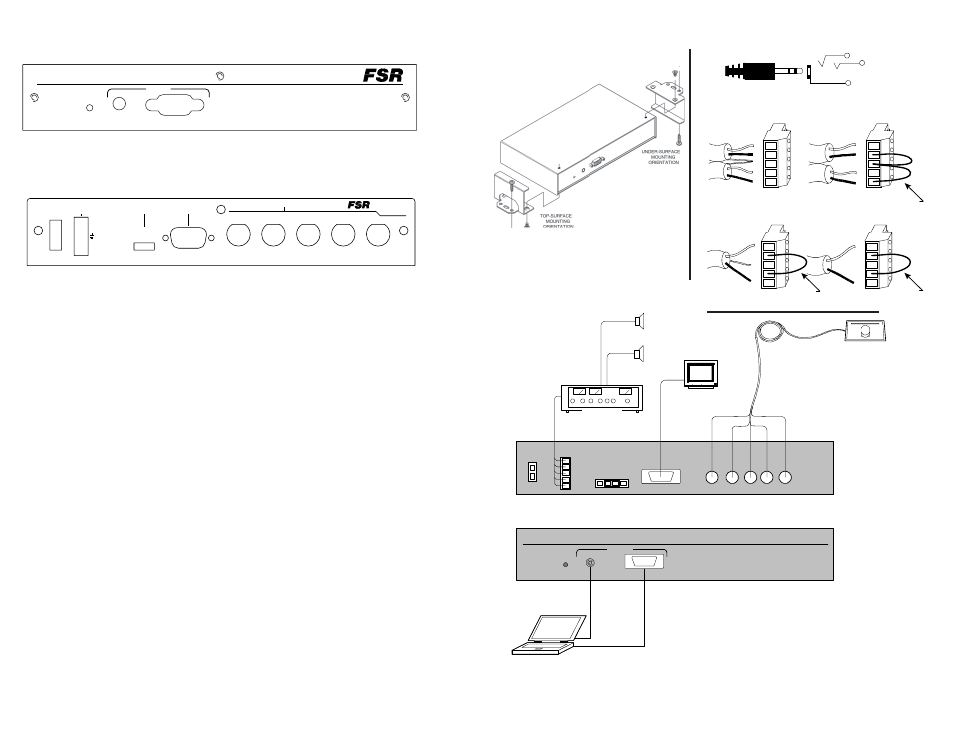
SET UP and INSTALLATION
Connect laptop or similar device to the front of the unit.
The 5 BNC output cable, 9 VAC power supply leads and audio
leads should be prewired prior to completing the steps below. Do
not plug in the power supply until all wiring is completed.
Connect the 5 BNC female connectors to the 5 BNC male output
cable leading to the projector or monitor.
Connect the audio output cables to the captive screw terminals
labeled “Audio Out”. The appropriate wiring configuration for
balanced and unbalanced connections is shown on the next page.
Set the cable equalization jumpers for optimum performance at the
desired cable length (OFF=0-60', LO=60-125', HI=125-175').
Connect the 9 VAC power supply output to the Power In connector
Confirm proper video and audio operation before mounting the CI -
5UT
Use the supplied brackets to mount the CI - 5UT to the underside
or topside of the table.
Perform the final operational check.
Front view
Rear view
MOUNTING DETAIL
TYPICAL INSTALLATION
VIDEO OUTPUT
Laptop
Monitor
COMPUTER A/V LINE DRIVER W ITH CABLE EQ
POWER
CI-5UT
FSR
POW ER IN
0.3A@9VAC
AUDIO
OUTPUT
CABLE EQ
GAIN
H
I
O
F
F
L
O
LOCAL MONITOR
OUTPUT
FSR
R
G
B
H
V
Projector
L
R
+
-
+
-
AUDIO
AMPLIFIER
CI-5UT COMPUTER A/V LINE DRIVER
TYPICAL APPLICATION
UP TO 175' CABLE RUN
AUDIO
INPUT
AUDIO
INPUT
COMPUTER A/V LINE DRIVER WITH CABLE EQ
POWER
CI-5UT
West Paterson,
V
N.J. 07424
244 Bergen Blvd.
Model CI-5UT
H
B
G
R
VIDEO OUTPUT
LOCAL MONITOR
OUTPUT
CABLE EQ
L
O
F
F
I
H
O
GAIN
AUDIO
POWER IN
L
-
+
R
+
9VAC/DC
OUTPUT
0.3A @
-
Tip = Left
Ring = Right
Sleeve = Gnd
L +-
+
-
R
SH
Unbalanced Input Connector Pinout
Output Connector W iring
L +-
+
-
R
SH
Balanced W iring
Unbalanced Wiring
L +-
+
-
R
SH
Mono Output Connector W iring
L +-
+
-
R
SH
Balanced W iring
Unbalanced W iring
Jumper
Jumper
Jumper