2 layout – Foxconn D70S Series User Manual
Page 11
PRODUCT INTRODUCTION
4
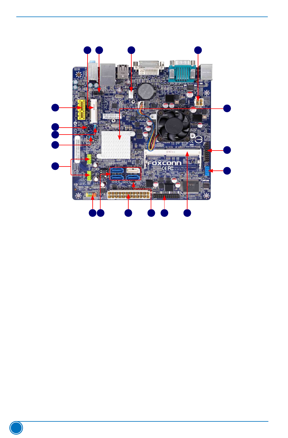
1-2 Layout
Note : The above motherboard layout is for reference only, please refer to the physical
motherboard for detail.
1. 4-pin ATX 12V Power Connector
2. System_Fan Header
3. Front Audio Header
4. MINI PCI Express Slot
5. PCI Express X1 Slot
6. Speaker Header
7. ME Header
8. Clear CMOS Header
9. Front USB Headers
10. Front Panel Header
11. SATA Connectors
12. 24-pin ATX Power Connector
13. INTR Header
14. LPT Header
15. DDR3 DIMM Slot
16. COM1 Header
17. TPM Header
18. Chipset: Intel® NM70
13
14
1
3
2
4
10
15
12
16
17
18
6
7
5
9
8
11
This manual is related to the following products:
See also other documents in the category Foxconn Motherboard:
- AHD1S-V (42 pages)
- 865PE7MF-SH (63 pages)
- 945P7AA-8EKRS2H (119 pages)
- 661FX7MF-S (64 pages)
- K7S741GXMG-6L (10 pages)
- 748K7AA-ERS (10 pages)
- NF3250GK8AA-EKRS (68 pages)
- 6100M2MA-RS2H (94 pages)
- NF4K8AB-RS (75 pages)
- K8S755M-6LRS (104 pages)
- 6497MB-S (107 pages)
- 945P7AA-8EKRS2H (106 pages)
- 755FXK8AA-ERS (108 pages)
- 760GXK8MC-RSH RAID (45 pages)
- 760GXK8MC-RSH (75 pages)
- 761GXK8MC-RSH (85 pages)
- CK804K8MA-KS (55 pages)
- NF3UK8MA-RS (70 pages)
- NF4XK8MC-RSH (68 pages)
- NFPIK8AA-8EKRS (110 pages)
- 761GXK8MB-RSH (87 pages)
- K8M890M2MA-RS2H (69 pages)
- K8T890M2AA-RS2H (62 pages)
- MCP61VM2MA-RS2HV (61 pages)
- N5VM2AA-KRS2H (2 pages)
- N570SM2AA-8EKRS2H (87 pages)
- C51XEM2AA-8EKRS2H (114 pages)
- 761MX (44 pages)
- 761GXM2MA-RS2 (65 pages)
- A6VMX (44 pages)
- A74ML Series (105 pages)
- A7VML Series (105 pages)
- A85GM (104 pages)
- A7VA-S (106 pages)
- A7VA-S (107 pages)
- M61PMP-K (111 pages)
- A7DA-S 3.0 (112 pages)
- A9DA-S (115 pages)
- Cinema II Premium (114 pages)
- A7VMX Series (106 pages)
- 720MX-K (112 pages)
- 720AL (110 pages)
- A79A-S (115 pages)
- 560A (46 pages)
- M61PMX (92 pages)