Fluke Biomedical 07-706 User Manual
Page 9
Introduction
Introduction
1
1-5
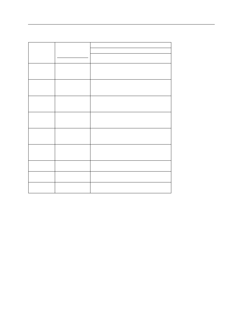
Table 2 Effect of Tube Potential, Distance and Filtration on Air Exposure Rate at Panel of
Fluoroscopes*
Equivalent Total Aluminum Filtration
1 mm
2 mm 2.5 mm 3 mm 4 mm
Potential
kVp
Source to
Panel
Distance
cm inches
Roentgens per Milliampere Minute
70
30 12
38 15
46 18
5.3 2.7 2.2* 1.8 1.3
3.5 1.7 1.4
†
1.2 0.8
2.4 1.2 1.0 0.8 0.6
80
30 12
38 15
46 18
7.0 3.9 3.2* 2.6 2.0
4.6 2.5 2.1
†
1.7 1.3
3.2 1.8 1.4 1.2 0.9
90
30 12
38 15
46 18
9.0 5.2 4.3* 3.6 2.8
5.8 3.3 2.8
†
2.3 1.8
4.0 2.3 1.9 1.6 1.2
100
30 12
38 15
46 18
11.0
6.6 5.5* 4.7 3.7
7.0 4.2 3.5
†
3.0 2.3
4.9 2.9 2.5 2.1 1.6
110
30 12
38 15
46 18
13.1
8.0 6.8* 5.9 4.6
8.4 5.1 4.4
†
3.8 3.0
5.8 3.5 3.0 2.6 2.0
120
30 12
38 15
46 18
14.7
9.3 8.0* 7.0 5.5
9.5 6.0 5.1
†
4.5 3.6
6.5 4.1 3.6 3.1 2.5
130
38 15
46 18
-- 6.8
5.9
†
5.2 4.2
-- 4.7 4.1 3.6 2.9
140
38 15
46 18
-- 7.6
6.6
†
5.9 4.8
-- 5.3 4.6 4.1 3.3
150
38 15
46 18
-- 8.5
7.5
†
6.7 5.4
-- 5.8 5.2 4.6 3.7
* Typical exposure rates produced by equipment with medium length cables, derived from references (8) and (14)
by interpolation and extrapolation. Filtration includes that of the tabletop and the x-ray tube with its inherent and
added filter. As used above, panel means either panel or tabletop.
Section 3.1.2(a) When the fluoroscope is operated at 80 kVp, the exposure rate in air at the position
where the beam enters the patient shall not exceed 3.2 R/mA-min at 30 cm and should not exceed 2.1
R/mA-min at 38 cm. For other tube potentials, the exposure per unit charge shall not exceed the values
marked with an asterisk (*) or a dagger (
†
).