6 safety related detectors, 7 commercial detectors – Fluke Biomedical 943-25 User Manual
Page 16
Victoreen 943-25, 943-26
Operators Manual
4-4
4.6 Safety Related Detectors
If the fault is isolated to the detector, repair can be performed by a technician rated to Skill level II as
described in Section 1.3, Specifications.
Any fault that cannot be isolated to the detector must be in the wiring to the readout or in the readout
itself. Consult the appropriate standard manual for the readout purchased so that the troubleshooting
procedure for that readout can be used. Defective wiring is replaced using the schematic diagram and
Table 4-1 as a guide.
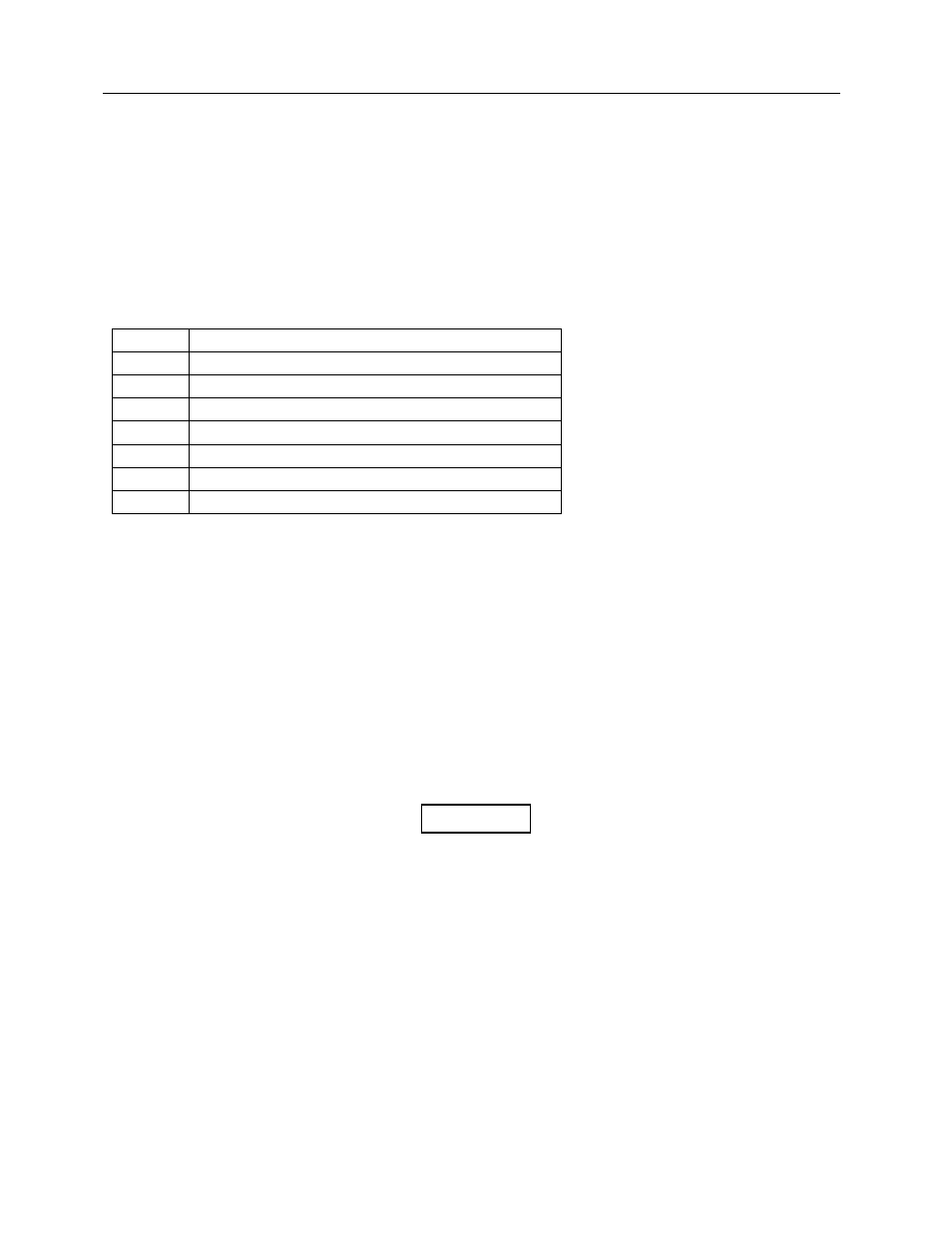
Table 4-1.
Cable Connector Pin Out
Pin Function
A High
Voltage
B High
Voltage
Shield
E
+15 VDC Supply
G
Power (± 15 V) Ground
F -15
VDC
C
Signal (Negative Pulses)
D Signal
Ground
4.7 Commercial Detectors
If the fault has been isolated to the detector, the following procedure can be used to identify the faulty
component. The schematic diagram in Appendix A can be used as a guide. Recommended test
equipment is listed in Table 4-2.
4.7.1 Preliminary
1. Turn off channel power at the readout.
2. Disassemble the detector according to Section 4.1.1, Detector Disassembly.
3. Remove and inspect the photomultiplier tube for visible signs of damage (cracks, excessive
rattling).
Do not replace the photomultiplier tube until
troubleshooting has been completed and power is
disconnected.
CAUTION