4 procedure - fluoroscopic, 5 image intensifier – Fluke Biomedical 07-661-7662 User Manual
Page 8
Nuclear Associates 07-661-7662
Operators Manual
1-4
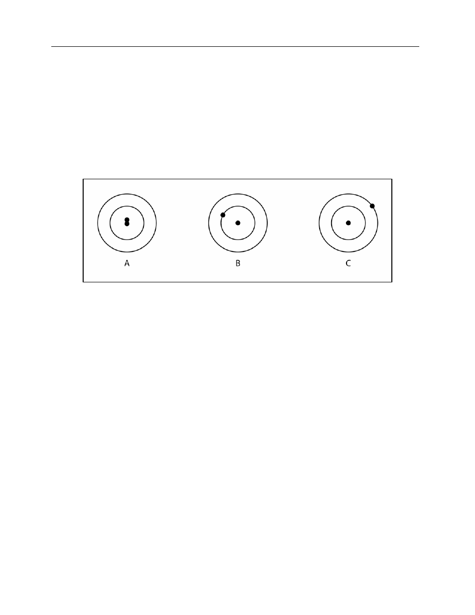
1.3.3 Beam Alignment
According to NCDRH specifications, the x-ray beam should be perpendicular to the plane of the image
receptor. If the image receptor is parallel to the tabletop, the perpendicularity of the x-ray beam can be
checked by using the Beam Alignment Tool with the Collimator Tool. The following criterion is applied for
a source-table distance of 40". If the images of the two steel balls overlap (Figure 1-5A), the central ray is
perpendicular to within 0.5°. If the image of the top ball (larger shadow) intercepts the first circle as shown
in Figure 1-5B, the beam is about 1.5° away from the perpendicular. If the image of the top ball intercepts
the second circle (Figure 1-5C), the misalignment is approximately 3°. See sample x-rays, Figure 1-2 and
Figure 1-4.
Figure 1-5. Interpretation of the Image of the Steel Balls in the Beam Alignment Test Tool
1.4 Procedure - Fluoroscopic
Collimation and alignment of the fluoroscopic image intensifier and spot film device can be checked with
the same two test tools used to check your radiographic unit.
1.5 Image Intensifier
For testing an under-the-table tube, the table should be level. Set the tools on the table, with the Beam
Alignment Tool in the center of the Collimator Tool (Figure 1-6). Center the image intensifier (30 cm or
12" above the table) over the tools by looking at the fluoro image (see Figure 1-6). The tools are on the
central ray of the x-ray beam when the images of both steel balls become one.