3 interpretation of results – Fluke Biomedical 07-661-7662 User Manual
Page 6
Nuclear Associates 07-661-7662
Operators Manual
1-2
1.3 Interpretation of Results
1.3.1 Collimation
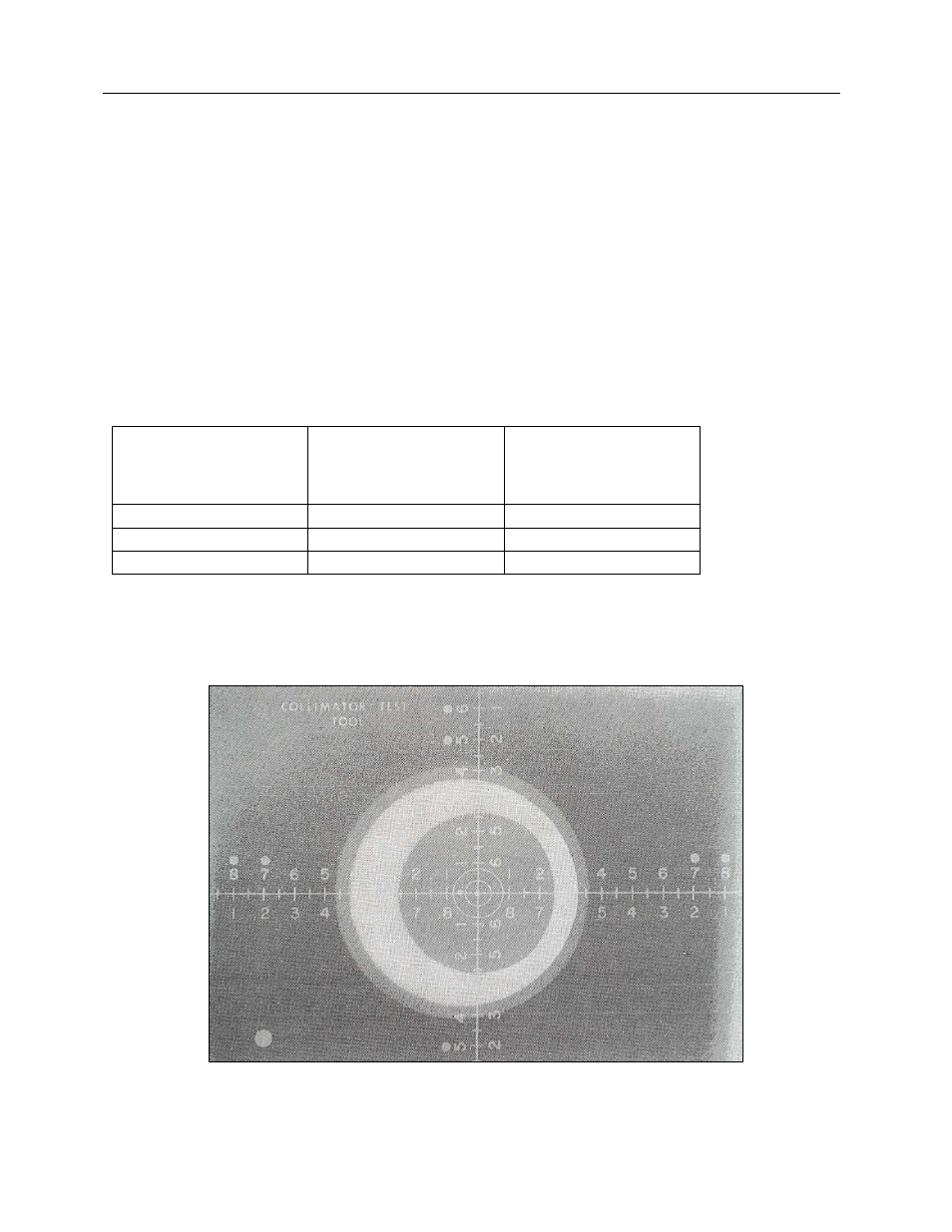
If the x-ray field falls just within the image of the rectangular frame, there is good alignment (Figure 1-2).
If an edge of the x-ray field falls on the first spot, ± 1 cm on either side of the line, the edges of the x-ray
and light fields are misaligned by 1% of the distance between the x-ray source and the tabletop.
Similarly, an edge falling on the second spot, ± 2 cm indicates an error of 2% at 40”. The maximum
misalignment allowed is 2% of the source-to-image distance (SID).
Alignment at one distance does not guarantee alignment at all other distances. It may be advisable to
repeat the test at other commonly used distances. Suggested exposures and allowable errors at different
distances are shown in Table 1-1.
Table 1-1. Suggested Exposures and Allowable Errors
Distance Between
Source
And Light Field
(Tabletop)
Exposure Factors
For RP Film
Maximum Misalignment
Allowed by BRH (2%)
91.4 cm (36”)
60 kVp, 10 mAs
1.8 cm (0.72”)
1.22 m (48”)
60 kVp, 14 mAs
2.4 cm (0.96”)
1.82 m (72”)
60 kVp, 38 mAs
3.6 cm (1.44”)
For a SID other than 40", the distance between the rectangular image and the edges of the x-ray field
should be measured with a ruler and compared to the value in the table for the given distance.
Figure 1-2. Good Field Alignment, Beam Alignment Approximately 2° from Perpendicular