Ptions and model numbers, Efault, Onfiguration – Flowserve 103 Smart Multi-Port IPS Wireless User Manual
Page 7
IPS WIRELESS SELD-103 ENGLISH 26999976 11-13
Page 7 of 20
flowserve.com
maximum data transmittal range of ¾ mile (1.2km)
under ideal conditions, but its effective
transmission range can be extended using a
network of repeaters.
Each SELD-103 can be part of a larger wireless
monitoring network. As such, each unit comes with
a calibration sheet from the factory which contains
unit-specific configuration information describing
the sensors and wireless network the unit is
configured for (parameters such as the wireless
system number, unit transmitter number, data
transmittal/check-in interval, scale factor and offset
to use with specific sensors). As long as your
specific application has been communicated to the
factory, the SELD-103 unit should come pre-
configured for your specific use.
3.1 Options and model numbers
The SELD-103 can either have wireless data
transmission enabled or disabled. In both settings,
it is compatible with all SELD-103 accessories.
SELD-103 units with wireless transmission
disabled (designated as SELD-103-VB) are
intended for use as local data collectors with either
the take away memory (VB-103-TAM) or visual
light alert modules (VB-103-VIS).
The SELD-103 is available with the following
sensors as options to connect to each port on the
unit:
1. Vibration & Temperature (RTD) Combination
Sensor
2. Vibration Sensor
3. Temperature Sensor (RTD)
4. Temperature Sensor (Thermocouple)
5. 4-20mA Analog Input Sensor
6. General Pulse Input Sensor
7. Tachometer (TTL)
8. Pressure & Temperature (RTD) Combination
Sensor
9. Discrete Sensor
10. Oil/Water Sensor
11. Vibration Sensor with FFT analysis output
12. Serial Port RS-485 Interface
13. Gas Sensor
Additionally the SELD-103 has the following
options available:
Table 1: Optional parts for SELD-103 unit
Part Number
Description
M1-0045
Magnetic Mounting Base,
Two-pole, 70 lbs (31.75 kg)
High Temp.
M1-0081
Unistrut Mounting Bracket
for SELD-103 unit, SS
casting base
M1-0085
SS cap for SELD-103
connection ports (single)
301-4024
Programming cable for
SELD-103
Unit: 5’ length,
Serial Port- RS-485
connection
PSP
SELD-103 Unit
Configuration Software
Utility
VB-103-TAM
Take-Away Memory Module
VB-101-DOCK
IPS Dock for communication
with VB-103-TAM Take-
Away Memory Module
TAM103
VB-103-TAM data download
and configuration software
VB-103-VIS
Visual Light Alert Module
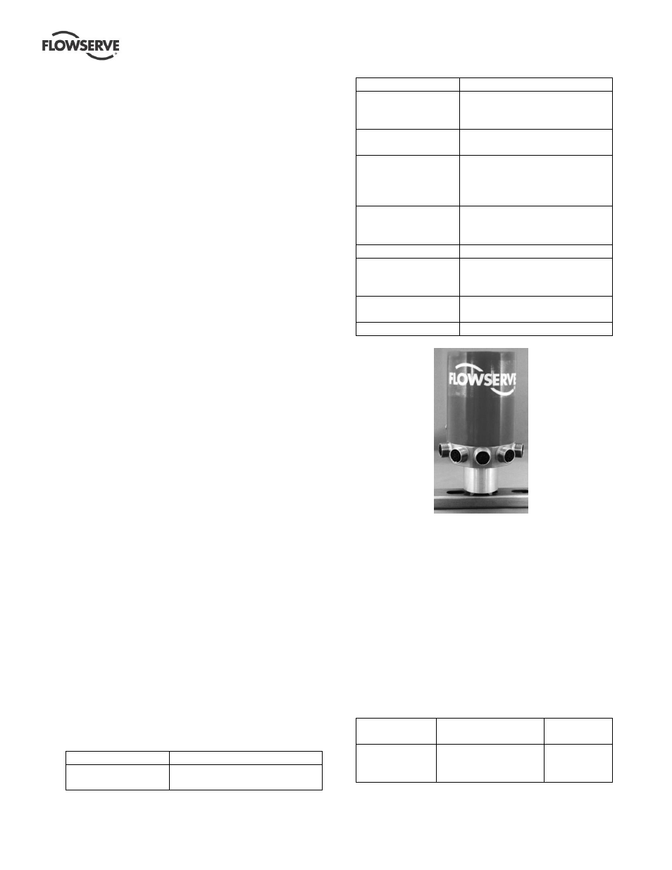
Figure 3: Magnetic mount option for SELD-103
unit
The exact configuration of different sensors
attached to each SELD-103 unit is limited to certain
combinations. Contact the factory for a complete
list of the different configurations available for the
SELD-103.
3.2 Default Configuration
The SELD-103 is configured to the following
parameters by default, unless otherwise specified.
Table 2: Parameter default configuration values
for SELD-103 unit
Parameter
Name
Parameter
Description
Default
Value
Normal
Measurement
Interval
How often data is
read from each of
the sensors by the
5 minutes