8 certifications, 9 trouble-shooting guide, Oss of – Flowserve 103 Smart Multi-Port IPS Wireless User Manual
Page 14: Ommunications
IPS WIRELESS SELD-103 ENGLISH 26999976 11-13
Page 14 of 20
flowserve.com
8 CERTIFICATION
The following certifications are applicable to the
SELD-103:
Table 7: Model SELD-103 certifications
0518
II 1 GD
Ex ia
CSA 2010 2273150
IECEx SIR.10.0006
Cl I, Zn 0 A/Ex ia IIC T6
I.S. for Cl I, Div 1 Grps A, B,
C, D;
Cl II, Div 1, Grps E, F, G;
Cl III, Div 1, and provides I.S.
circuits with Entity
Parameters per Install
Manual 701-2000 and 701-
3000
Tem. Code T6
-2
0°C ≤ Ta ≤ +60°C
Sira 10ATEX2013
Ex ia IIC T6 Ga
Ex iaD IIIC T85°C DA
9 TROUBLE-SHOOTING GUIDE
EXPLOSION HAZARD: The unit must be
powered OFF during the battery installation & must
be in a General Purpose Classified Area before
removing outer plastic tube to prevent the possible
ignition of a hazardous atmosphere.
9.1 Loss of Communications
Loss of communications with SELD-103 unit may
occur for several reasons:
Unit not powered up
Unit not configured correctly
Unit out of range of receiver
Receiver not configured correctly
See solutions below to each of the possible
causes:
9.1.1 Unit Not Powered Up
Verify set screw is installed at base of SELD-103
unit (see section 4 MAINTENANCE on how to turn
on unit).
1. Connect diagnostics RS-485 cable to port 6 of
SELD-103 and other end to a PC.
2. Read battery level using PSP software. If the
battery level is above 2.8V, skip to step 8. If
you are able to successfully read the battery
voltage on this screen but the level is below
2.8V, replace the battery according to
instructions in section 4 MAINTENANCE.
3. If communications are still not successful,
power down unit by removing the magnetic set
screw located at the bottom of the base.
4. Remove sensor cable(s) and configuration
cable.
5. Ensure SELD-103 is in a non-classified area
before performing next step.
6. Loosen the set screw in the side of the tube
and gently unscrew the external housing (tube)
from the transmitter assembly.
7. The battery pack should be visible on the lower
end of the transmitter assembly. Carefully
disconnect the battery pack.
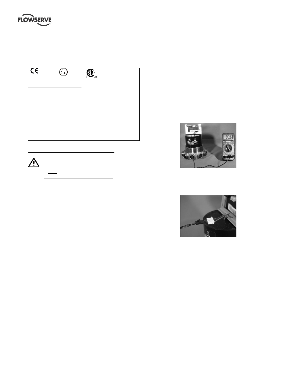
8. Use a voltmeter to read battery voltage across
pins with red and black wires on connector to
battery pack. If the voltage level is below 2.8V,
replace the battery according to instructions in
section
Figure 13: Measuring battery level on SELD-103
unit (external housing removed) using a
voltmeter
Figure 14: Detail view of voltmeter connection
to battery pack cables.
9.1.2 Unit Not configured Correctly
To perform the diagnostic steps for this issue, the
SELD-103 unit will need all sensors connected to it.
Refer to PSP software instructions to reload the
original configuration into the SELD-103 unit.
9.1.3 Unit Out of Range of Receiver
I
f communications from the SELD-103 unit to the
receiver are still not successful, physically move
the SELD-103 unit next to and with a clear line of
sight to the receiver.