Electrical connection, A b s, Ort 7 basis org ort 7 cpu – Flowserve OR 52-7 User Manual
Page 13: Separator gps
3
Electrical Connection
– continued –
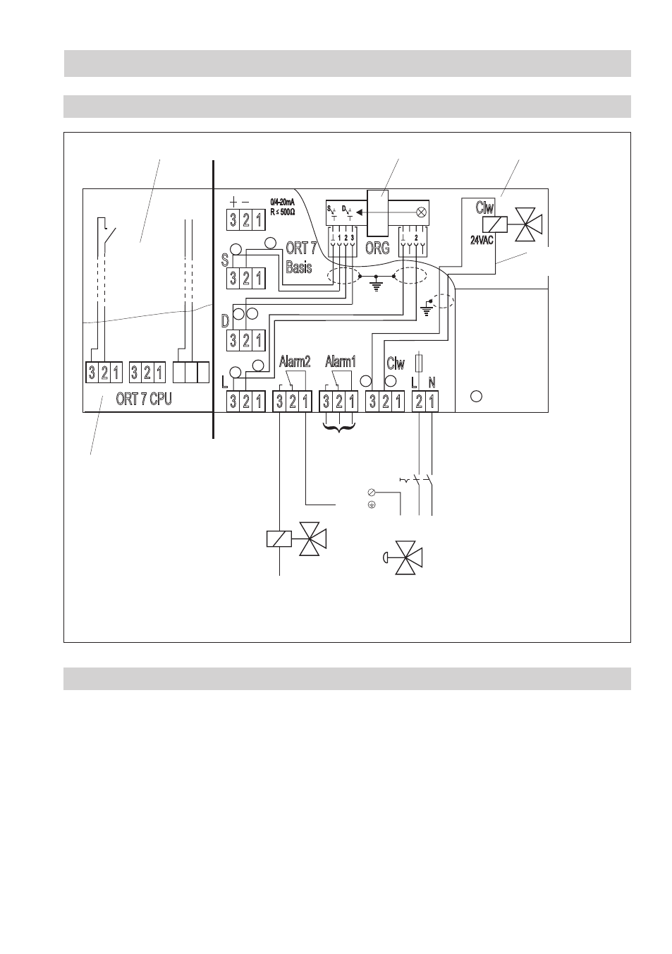
Wiring diagram OR 52-7
Fig. 4
Shown position of contacts: Alarm 1 and 2, separator OFF and power failure
Notice
Fig. 4 shows an example where the water will be run back to the ship‘s bilge in the event of an alarm
(oil content > 5 ppm) or auxiliary power failure.
With different limit settings alarm contact can, for instance, be used for the first alarm and alarm
contact 2 for the main alarm.
For bilge water monitoring a pneumatic three-way valve can be controlled by the alarm contact 2 via a
solenoid valve. If the turbidity of the effluent is too high (alarm caused by ingress of oil or dirt particles
introduced into the system during start-up) the three-way valve will divert the contaminated water to
the bilge tank. The separation continues until the oil content falls below 5 ppm and the cleaned water
can be discharged overboard.
D
S
1 2
2
3
3
3
3
3
3
3
3
L N
0/4-20mA
R 500
2
2
2
2
2
2
2
2
1
1
1
1
1
1
1
1
S
D
L
Alarm2
Alarm1
ORT 7
Basis
ORG
ORT 7 CPU
A B S
Separator
GPS
1
1
2
2
3
3
key “+” :
Clw - On
key “-” :
Clw - Off
Clw
24VAC
Clw
1
2
2
1
3
4
1
- wire no.
1
2
External wiring
Measuring sensor
Disconnecting switch
External
wiring
Purging valve
To first alarm
Attached in housing
cover
Solenoid valve
Three-way valve
Earthing screw
in housing
PE L N
N
L