Fig. 1, Fig. 2 – Flowserve NRS 1-50 For ONE Electrode User Manual
Page 6
6
Functional Safety acc. to IEC 61508
Safety characteristics of the subsystem NRG 1...-50 / NRS 1-50
The level switch NRS -50 is certified acc. to IEC 6508 if used in combination with level electrode NRG
...-50 / NRG 6-36.
The combination NRG ...-50 / NRG 6-36 / NRS -50 corresponds to a type B subsystem with Safety
Integrity Level (SIL) 3. Type B means that the behaviour under fault conditions of the used components
cannot be completely determined. The functional safety of the equipment combination refers to the de-
tection and evaluation of the water level and, as a consequence, the contact position of the output relays.
The design of the equipment combination NRG ...-50 / NRG 6-36 / NRS -50 corresponds to the ar-
chitecture oo D.
This architecture consists of two channels that detect and diagnose faults in each other. If a fault is de-
tected, the equipment combination NRG ...-50 / NRG 6-36 / NRS -50 will go to the safe state, which
means that the contacts of both output relays will open the safety circuit.
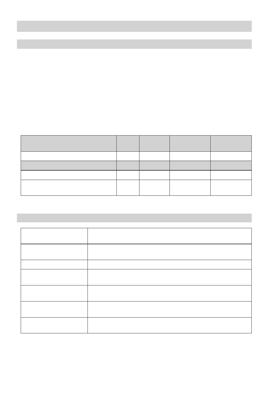
Safety characteristics
SIL
Architecture
Lifetime
(a)
Proof Test
Interval (a)
General
3
oo D
0
0
SFF
PFD
av
PFH
av
λ
DU
Level switch NRS -50 alone
98.54 %
.8 x 0
-4
3.73 x 0
-8
7.33 x 0
-8
/h
Level switch NRS -50 in conjunction with
one level electrode NRG ...-50, NRG 6-36
98.7 %
.69 x 0
-4
4.54 x 0
-8
9.33 x 0
-8
/h
Fig. 1
Terms and abbreviations
Terms
Abbreviations
Description
Safety Integrity Level
SIL
Classification of the Safety Integrity Level acc. to IEC 6508
Lifetime (a)
Functional safety: Lifetime in years
Safe Failure Fraction
SFF
Percentage of failures without the potential to put the safety-related system into
a dangerous state
Probability Failure per Demand
(Low Demand) PFD
av
Average probability of failure on demand for low demand mode (once a year)
Probability Failure per Hour
PFH
av
Probability of failure per hour
λ
DU
Failure rate for all dangerous undetected failures (per hour) of a channel of a
subsystem
Fig. 2