Flowserve ACE Series Centura User Manual
Page 7
©
2004, Flowserve Corporation, Printed in U.S.A.
3-Position Control/Dribble Control
SR Limit Switch Method
Accord Controls
Installation, Operation and Maintenance Instructions
Flowserve Corporation
1350 N. Mountain Springs Parkway
Phone: 801 489-2234
Flow Control Division
Springville, Utah 84663-3004
Facsimile: 801 489-2228
www.flowserve.com
FCD ACAIM0075-00 (AC-75) 08/04
Page 7 of 8
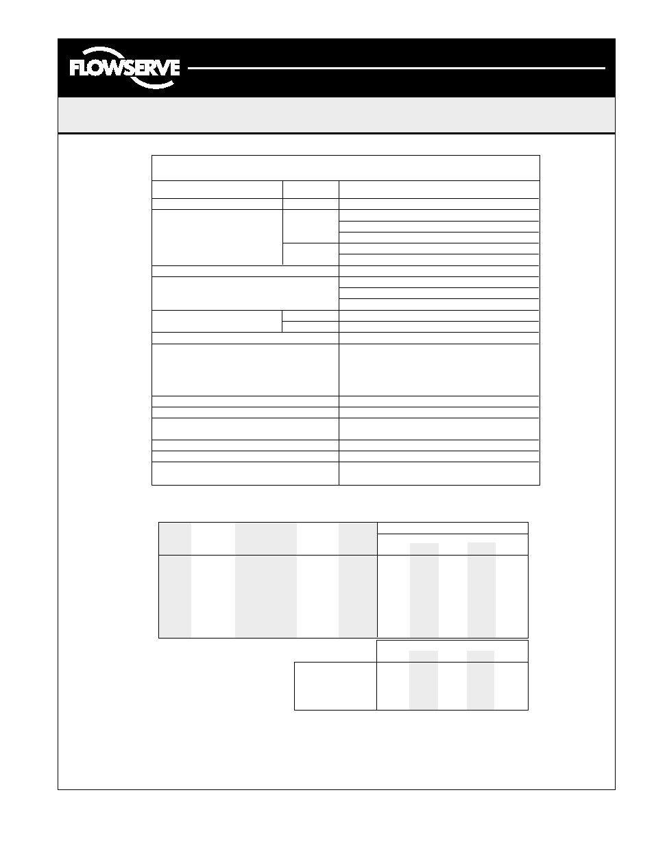
Typical Actuator Specifications
Action
Reversible
Range of Adjustability
0
°
-270
°
Supply Voltages
AC:
115 VAC
+/-10%
230 VAC
50/60 Hz
24 VAC
DC:
12 VDC
24 VDC
Temperature Rating
-40
°
F (-40
°
C) to 160
°
F (70
°
C)
Enclosure Ratings
Nema 4, 4X, 7, 9 Watertight and Explosion-proof
Class I Groups C&D, Div. 1&2
Class II Groups E, F&G, Div. 1&2
Motor Types
AC:
Permanent Split Capacitor, Class B Insulation
DC:
Brush
AC Motor Thermal Protection
Automatically resetting
Travel and Aux. Switches
SPDT, Form C
15 amp 125 VAC 1/2 HP,
10 amp 250 VAC, 1/2 amp 125 VDC
Conduit Connections
3/4-14 NPT
Manual Override
300 In-lbs max input
Corrosion Protection
Chromate conversion undercoat with
polyester electrostatic powder top coat
Terminal Strip Hookup
300V, 30 amp, 12-26 AWG
Lubrication
Permanently lubricated
Gear Train
Heat treated alloy steel able to
withstand stall torque
Note: The above ratings may change depending on model configurations and options provided.
Products may differ as the result of the Company policy of continuous product improvement.
Notes:
1. Duty cycle is the limit of “on” time as percentage of total cycle time. For example, the CE2 with standard
motor runs 3 seconds to open or close the valve. The motor must remain off for 9 seconds prior to
starting the close cycle. DC motors may be operated continuously.
2. Do not lock up DC motors.
3. CE5 duty cycles for AC motors are 20% for standard duty and 70% for extended duty.
4. For 180 degree applications, simply multiply the above cycle times by 2.
Run
Locked
Cycle Times in Seconds per 90 Degrees
Motor
Motor
Duty
Current
Rotor
Actuator Model
Option
Voltage
Cycle (1, 3)
(Amps)
(Amps)
CE2
CE4
CE7
CE1
CE5
Std.
115 AC
25
1.1
1.3
3
5
6
11
18
A
115 AC
Extended: 75
0.5
0.6
6
10
17
24
36
B
12 DC
100
1.6
3.0 (2)
6
9
16
21
32
C
24 DC
100
0.9
2.0 (2)
6
8
15
20
30
D
230 AC
25
0.7
0.8
3
5
6
11
18
F
230 AC
Extended: 75
0.3
0.4
6
10
17
24
36
J
24 AC
100
0.5
0.8
3
5
6
11
18
Actuator Model
CE2
CE4
CE7
CE1
CE5
Torque (In-Lbs)
250
400
700
1000
1500
Torque (N-M)
28
45
79
113
169
Weight (Lbs)
18
18
18
18
20
Weight (Kg)
8
8
8
8
9