Operation, Air requirements, Front cover and indicator cover – Flowserve PM15E Electro-Pneumatic Valve Positioner User Manual
Page 4: Worcester controls
before pressurizing. A high flow silencer or an exhaust pipe can
be connected to this port to prevent foreign objects from entering
and blocking the unit’s exhaust.
When using gases other than air for supply, please contact
Worcester.
Connect the air supply line to port S.
For double-acting operation, connect the right-hand and the left-
hand ports of the actuator end cap (right-hand end cap when
facing actuator nameplate) to ports C2 and C1 respectively.
For single-acting operation, plug port C1 for increasing signal to
open or close. Plug C2 for decreasing (reverse) signal to close.
The 4-20 mA signal wires will be connected to the terminal block
by passing the wires through port I
E
. Be certain that you observe
proper polarity when making the connections. Remove cover (62)
for access.
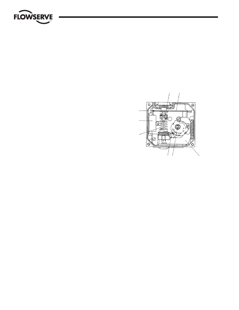
3. OPERATION
The PM15E operates on a force balance principal. Force is originated
by the signal pressure transmitted through a diaphragm onto the
balance arm. The opposing force is achieved through the feedback
spring and is proportional to the position of the lower arm. The lower
arm position is determined by the position of the cam which is
secured to the spindle and connected to the actuator shaft, thus
providing the feedback from the actuator/valve. When these two
forces are equal, the balance arm and the spool in the pilot valve are
in neutral position—the complete unit is in a balanced position. Air is
supplied to the pilot valve through port S, and controls the air flow
through ports C1 and C2.
Assume an equilibrium position.
An increased control pressure will deflect the diaphragm (1) down,
compressing the feedback spring (3). The balance arm (2) moves the
spool (7) in the pilot valve (8) furnishing supply air to the actuator,
while at the same time air is exhausted from actuator and is vented to
atmosphere through the pilot valve and the OUT port.
With the increased supply air, the actuator rotates (or moves linearly),
moving the positioner spindle (6). The spindle and cam (5) rotate,
forcing the lower arm (4) upwards, compressing the feedback spring
(3). This motion will continue until two forces are equal and the unit is
an equilibrium position.
4. AIR REQUIREMENTS
Maximum supply pressure is 0.9 MPa (125 psi).
Supply air shall be clean, dry and free from oil, water, moisture,
foreign parts and debris.
The air shall be freeze-dried or similar to a dew point of at least 10°C
(18°F) below lowest expected ambient temperature.
A < 40 micron filter/regulator is recommended to be installed as close
to PM15E as possible to ensure proper supply air quality.
5. FRONT COVER
AND INDICATOR COVER
The front cover of the PM15E is secured to the pneumatic unit with
four captured screws and sealed with an O-ring (1). The O-ring can be
looped over notches (2) in the front cover to allow for drainage. There
are eight locations on the front cover where the O-ring can be looped.
This O-ring system is common to the pneumatic unit and I/P unit in
the PM15E. This unique sealing system allows for complete sealing or
draining of the units by changing the position of the O-ring.
The indicator cover (3) is O-ring sealed and secured by a bayonet
coupling. The indicator cover is also used to secure the identification
cover (4).
To remove the indicator cover, turn it slightly counterclockwise until it
loosens. Identification cover and O-ring (5) are now removable. When
installing indicator cover and identification cover, make sure that the
O-ring is properly engaged.
Flow Control Division
Worcester Controls
4
Model PM15E Electro-Pneumatic Valve Positioner
WCAIM2017
8
7
1
2
4
6
5
3