M.a.s. positioner/controller options, Installation, Worcester controls – Flowserve 90 Series Controller User Manual
Page 4
4
Positioner/Controller for Series 90 Modular Accessory System
WCAIM2045
5.M.A.S. POSITIONER/CONTROLLER
OPTIONS
a. As a Positioner Board
The M.A.S. positioner/controller board as manufactured by
Flowserve is set up as a positioner that will accept a
4-20 mA position input control signal and use a 1000 ohm
feedback potentiometer. However, the board can be set up with
input signal options for 1-5 mA, 10-50 mA, 0-135 ohm,
0-1000 ohm, 0-5 volt, or 0-10 volt.
b
As a Controller Board
The M.A.S. positioner/controller board can also be configured as
a single-loop controller. The sensor input signal options available
are the same as for the positioner only now the signal comes
from the process transmitter. The standard process signal input is
set up for 4-20 mA.
Setpoints: The controller will accept setpoint inputs of either
4-20 mA or 0-1000 ohm potentiometer. The standard setpoint
input is the 0-1000 ohm potentiometer, which is provided with the
unit and externally mounted at a location chosen by user. For the
optional 4-20 mA setpoint, the 0-1000 ohm potentiometer is not
provided; customer provides 4-20 mA setpoint signal.
6.INSTALLATION
Note: All wiring is to be run smoothly and neatly and away from any
rotating parts. Use caution to avoid pinching the wires and/or
solenoid rectifiers between the base and cover flanges.
a. General – If the M.A.S. package was purchased with the
positioner/controller circuit board factory installed, proceed to
section 7, Adjustment.
b. Mounting the Positioner/Controller Circuit Board
It may be preferable to wire the circuit board to the terminal strips
before mounting the circuit board to the M.A.S. baseplate. This can
be done with the baseplate removed from the housing if desired.
Refer to Figure 1 below.
1. Insert #4 x
C\," self-tapping screws (item 1) through the top
four screw holes in the insulating sheet (item 2). Carefully fit
the M.A.S. Positioner/Controller circuit board (item 3) over
these screws as well.
2. Attach the circuit board/insulator assembly to the vertical
mounts (item 4) on the baseplate (item 5) and tighten the
four screws.
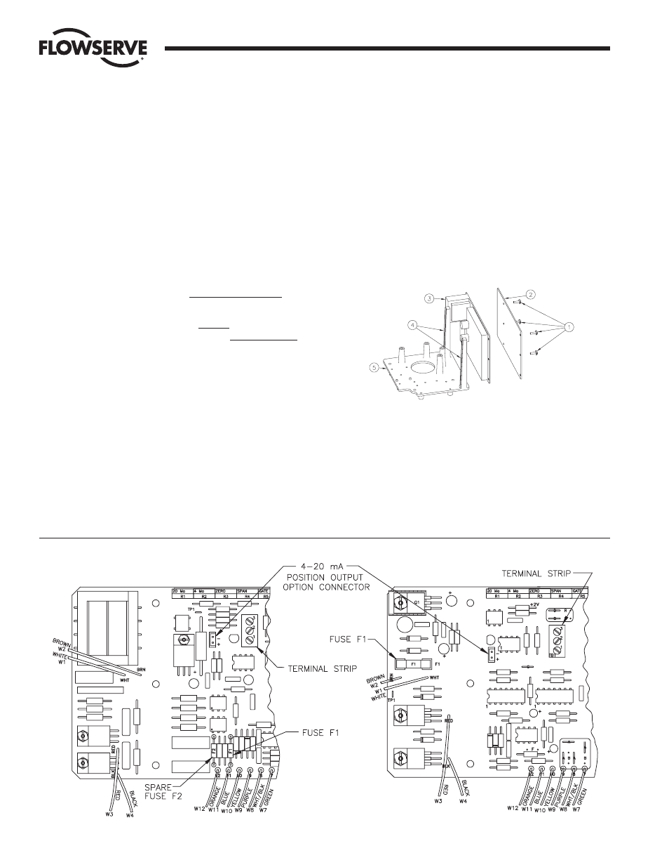
3. Connect the wires to the terminal strips per the appropriate
wiring diagram. Refer to section 11 for wiring diagrams.
Note: If the 4-20 mA position output option is being used,
then wires from potentiometer “B” of Dual Potentiometer (if
positioner), or single potentiometer (if controller) will be
connected to the three-point terminal strip on the positioner/
controller board as follows: Green from potentiometer to
terminal 1 (bottom); Wht/Blk from potentiometer to terminal 2
(middle); Purple from potentiometer to terminal 3 (top).
Flow Control Division
Worcester Controls
Figure 1
Figure 2
AC Board
DC Board