Flowserve WRG Series Standard Actuator User Manual
Page 9
9
®
User Instructions WRG Series Standard Actuator - WCENIM0123-00 12/12
4.2.4 Bolt up the cylinder flange on the thrust base of the
Spring Module using the using the lock washers and
nuts from override mounting kit.
4.2.5 Thread in the hydraulic connector into the cylinder port
and connect it to the power pack, as per the schematic.
4.2.6 Fit the 3 way valves supplied in the mounting kit, to the
pressure module’s ports, as per the schematic.
4.2.7 Fill to level, hydraulic fluid (ISO 32 grade for general
application) in the power pack reservoir, in the full re-
tracted position of the piston.
4.2.8 Verify the maximum hydraulic pressure setting for the
actuator model (refer table), close the pressure release
valve on the pump and operate the hydraulic pump to
start the ram movement. Lightly loosen the air vent
screw on the cylinder flange to bleed off air from the
hydraulic lines. The ram touches the Pull Rod’s end
face and pushes the pull rod, effecting the override.
4.2.9 Adjust the overload valve setting on the pump to en-
sure the pressure does not grossly exceed the Hydrau-
lic pressure setting for the actuator, at the end of the
stroke when the stopper bolt gets loaded.
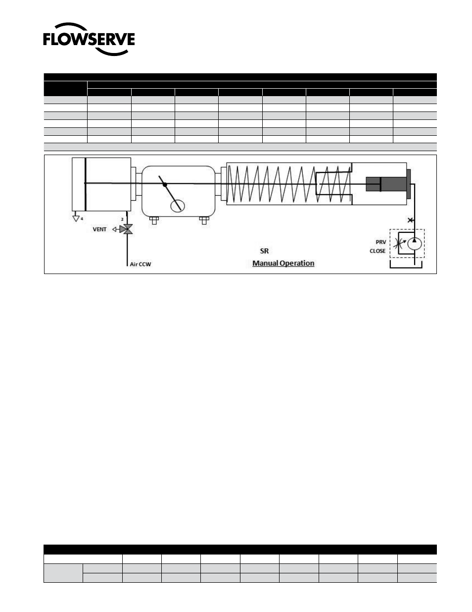
4.3 Operation –SR Override
4.3.1 To operate the override, turn the 3/2 way valve on pres-
sure module to vent the cylinder port to atmosphere and
Close the pressure release valve, PRV (provided either
externally or integral with the hand pump). Operating the
Hand Pump on the power pack pushes the pull rod, com-
presses the spring and operates the valve.
4.3.2 Opening the pressure release valve, PRV releases the hy-
draulic pressure and the spring returns the actuator to fail
safe state and the piston rod of override cylinder to retracted
position.
4.3.3 To restore normal Automatic operation, turn the PRV
to Open and switch the 3/2 way valve in position to
connect cylinder port to air supply pressure.
4.4 Install hydraulic override on Standard DA heavy
duty actuator
4.4.1 Remove the DA cover plate from the torque module
and mount the DA hydraulic override cylinder assem-
bly with the mounting kit and flange O-ring in the face
groove.
Hydraulic Pressure Settings for SR Models, psi
Model
Spring Module
1
2
3
4
5
6
7
8
WRG3
1550
2000
2400
2850
3000
3000
3000
WRG4
1350
1580
1950
2200
2450
2900
3000
3000
WRG5
1200
1680
2000
2300
2900
3000
WRG6
1000
1550
1900
2200
2500
2800
WRG7
1050
1750
2000
2350
2800
3000
WRG8
1150
1800
2300
2700
2900
3000
Hydraulic MOP: 3000 psi
Piston rod/pull Rod Torque
Hex Size, A/F
18
18
24
30
36
46
65
85
Tightning
torque
ft Lb
30-35
35-45
50-60
60-75
75-85
100-140
175-200
200-240
kgm
4-5
4-5
7-8
8-10
10-12
13-19
24-28
28-33
Fig.: 2 Install Hydraulic Override (SR)