Disassembly procedures, Reassembly procedures, Changing number of spring – Flowserve SX-Series SuperNova User Manual
Page 2
Flowserve Corporation
765 South 100 East
Phone: 801 373 3028
Flow Control Division
Provo, Utah 84606-6160
Facsimile: 801 489 2228
Automation Business Unit
www.flowserve.com
Email: [email protected]
© 2001, Flowserve Corporation, Provo, Utah
Automax Valve Automation Systems
Installation, Operation and Maintenance Instructions
Maintenance Instructions
Disassembly Procedures
1. Disconnect all air and electrical supplies from actuator.
2. Remove all accessories from actuator and dismount actuator
from valve.
3. Position actuator with air supply ports facing you. Apply air
pressure to Port 2 to release spring pressure from the Stop
Bolt (9).
4. Remove the Stop Bolt Retaining Nut (14), Washer (15),
and O-ring (16) on the Left Endcap (19) and turn the Stop
Bolt (9) clockwise into the Body (1) until it is flush with the
Endcap (19).
5. Exhaust air from Port 2, the Stop Bolt (9) should now turn
freely. Continue turning Stop Bolt (9) clockwise until it is
disengaged from the Endcap.
CAUTION: Unload springs before removing pinion to eliminate
possible spring side loading that could scratch the
pinion bore.
6. Spring Return Actuator:
CAUTION: Follow step 4 to relieve force on inward travel stop
before proceeding.
CAUTION: Do not use impact wrench to remove endcap screws.
Failure to follow this precaution could result in bolts
binding in the body.
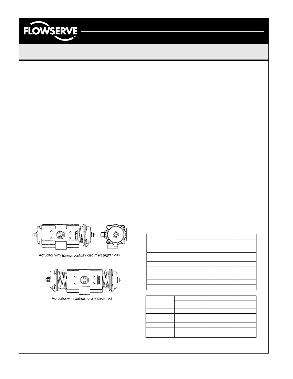
To remove Spring Return Endcap, first completely remove
two diagonal Endcap Screws (21) from one Endcap. The two
remaining Endcap Screws should be removed evenly. As
the Screws are removed, the springs will push the Endcap
out. Repeat for opposite side. The springs will be totally
unloaded before the screws are completely unthreaded.
Remove the springs (23,24,25.)
Double Acting Actuator: Remove the 8 Endcap Screws (21). Step
7 will push the Endcaps (18,19) from the Body (1).
CAUTION: Do not use impact wrench to remove endcap screws.
Failure to follow this precaution could result in bolts
binding in the body.
7. Rotate Pinion (3) counterclockwise (DA & SR-FCW) or
clockwise (DR & SR-FCCW) to drive the Pistons (2) off the
end of the rack. Pull the Left Piston (2) from the body (1) by
Reassembly Procedures
1. Inspect all parts for wear and replace any worn parts as needed.
Replace all ‘O’-rings.
2. Clean all components and lightly grease cylinder bore, pinion and
seals with a high performance grease such as Dow 55. Lubricate
endcap screw (21) threads with similar grease.
3. Reverse the disassembly procedures to reassemble.
4. The standard Pinion (3) orientation is with the flats on top of
pinion perpendicular with the body (1) in the CW position.
5. When fitting the Pistons (2) ensure the teeth engage the Pinion
(3) at the same time by measuring in from the edge of the body
(1) the same distance from each end. Note: the orientation of the
pistons will determine the operation of the actuator. Refer to the
diagrams under “Operation” for correct piston position.
6. Test the actuator for smooth operation and air leakage at service
pressure before installing.
Changing Number of Spring
1. Follow the Disassembly Procedures through step 5.
2. Determine nested spring combination of inner, middle and outer
springs. Consult catalog torque charts, distributor or factory.
Insert appropriate springs into cylinder. Springs must be
properly seated against piston and endcap to assure that
springs do not bind.
3. Re-assemble the actuator.
➁ SX050 has maximum of 2 springs per
endcap
➁ Install springs on opposite sides
Note: ➁ #1 Spring has one color code dot
#2 Spring has two color code dots
#3 Spring has three color code dots
Spring chart SX063-SX150
Spring Combination ➁
Spring Group
#1 Spring
#2 Spring
#3 Spring
(inner)
(middle)
(outer)
4 2
5
1➁ 1➁
6
2
7
1
2
8
2
2
9
1➁ 1➁ 2
10
2
2
11
2
2
12
2
2
2
Spring chart SX050 ➁
Spring Combination ➁
Spring Group
#1 Spring
#2 Spring
#3 Spring
(inner)
(middle)
(outer)
4
1➁ 1➁
5
2
6
2
1
7
1
2
8
2
2
9
2
2
Page 2 of 4
LMR0021-1 (AUTO-6) 11/01
pulling on the Stop Bolt (9).
8. Remove the Right Piston (2) by pushing out through inside
of Body (1).
9. Remove the Pinion Snap Ring (5) and Pinion Washer (4), and
pinion thrust washer (26).
10. Tap Pinion (3) lightly with plastic mallet to remove.