Assembly, 1 handwheel shaft assembly and shimming – Flowserve L120-85 Actuator User Manual
Page 31
Assembly should be conducted in the reverse order of the disassem-
bly procedures noting the following points:
8.1 Handwheel Shaft Assembly
and Shimming
If you have disassembled the Clutch Latch Assembly (pieces 32-1,
32-2 and 33) or have replaced the Handwheel Shaft Assembly,
Clutch Pinion Assembly (piece 18), Clutch Assembly (piece 19) or
Motor Cam (piece 38) you need to re-shim the Handwheel Assembly
using the following procedure:
1. Remove the Retaining Ring (piece 4-3), Handwheel Spacer
(piece 4-2), Handwheel Shims (piece #s 6-1 and 6-2), Hand-
wheel Bushing (piece 4-1), O-rings (piece #s 43 and 44) and
second group of Handwheel Shims (piece #s 6-1 and 6-2) from
the Handwheel Shaft Assembly. Refer to the Illustrated Parts
Breakdown for additional views.
8
Assembly
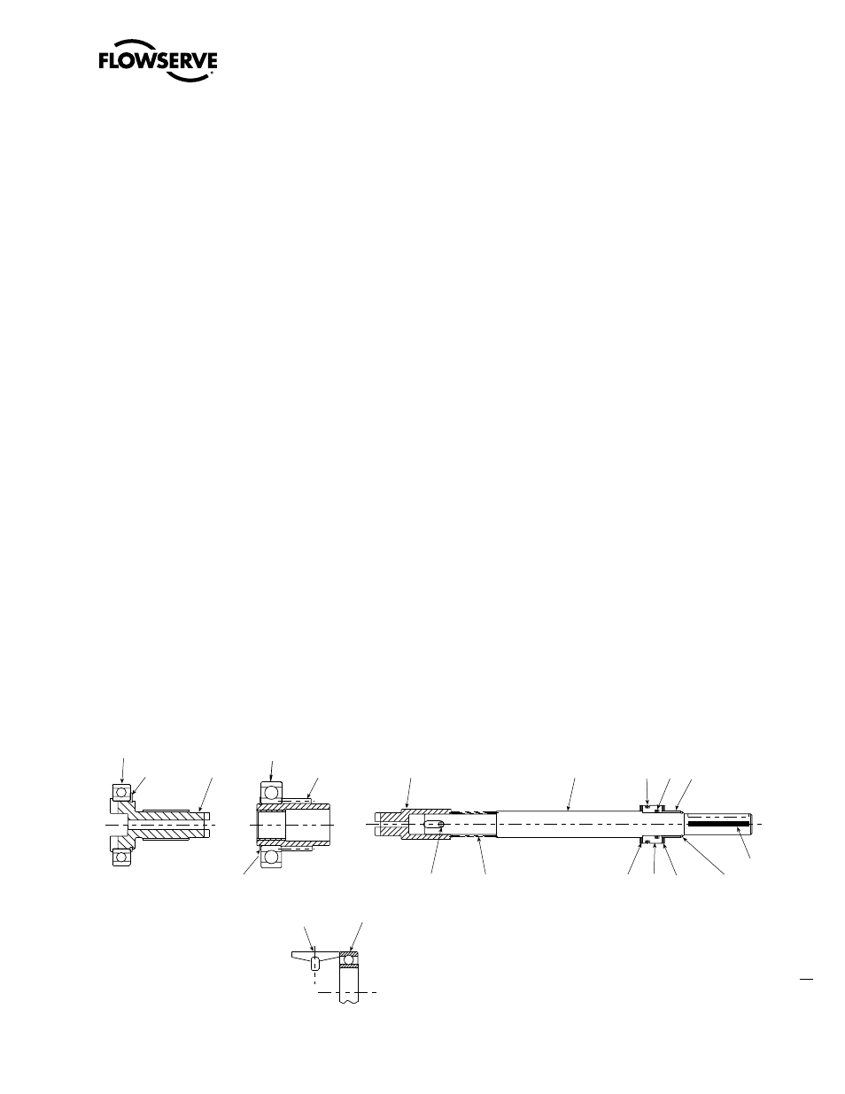
Figure 18: Key components affected by Handwheel shimming (Motor Cam not shown)
Clutch Assembly
Clutch Pinion
Assembly
Handwheel Shaft
Assembly
Position of Latch for shimming
Handwheel Shaft
3-3
3-2
2-1
4-1
44 43 4-2
4-3
18-2
18-1
19-2
19-3
19-1
3-1
18-3
6-1
2-2
6-1
32-1
19-2
(qty. 1)
(qty. 5)
1
Limitorque L120-85 Installation, Operation and Maintenance FCD LMENIM1202-00 – 11/05
flowserve.com