Flowserve NAF-Turnex pneumatic actuators User Manual
Page 9
9
10
9
4
8
2
7
6
1
3
5
3a
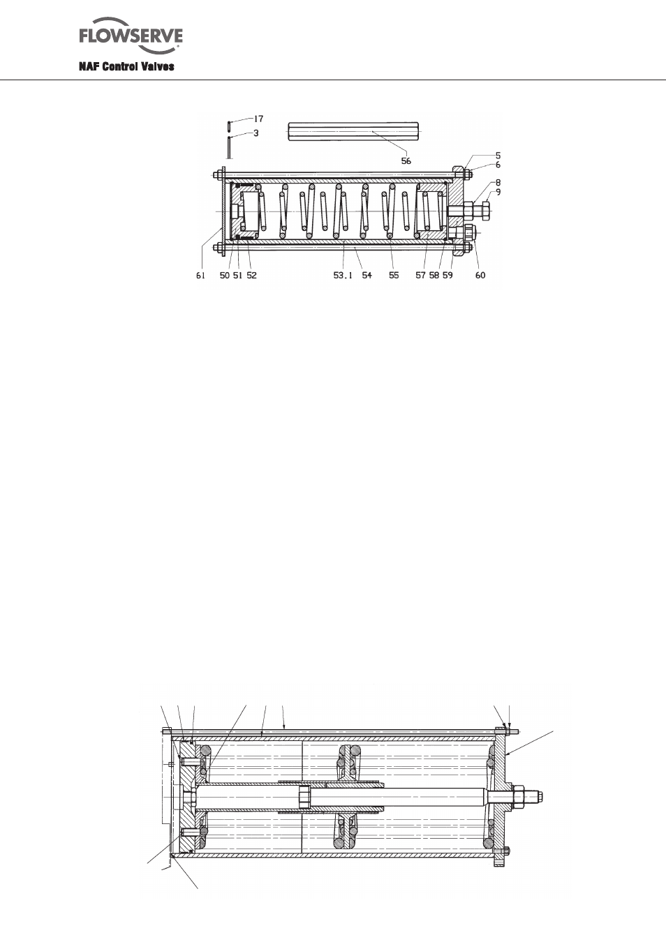
Fig. 10. Complete spring-return unit in sizes 0 and 1 - 3
5. Place the complete spring assembly (3) with its guide
pins (3a) in the corresponding holes in the piston.
Turn the assembly and piston so that the tie rods (4)
are at right angles to the end cover of the actuator
box and so that they move freely in the end cover of
the assembly. Without turning the piston, remove the
spring assembly from the piston. Tighten the piston
rod nut (2) without turning the piston.
6. Grease the end-cover O-ring (5) as described in
section 2.6, and fit it to the end-cover guide of the
actuator box.
7. Fit the piston guide (6- in two parts) into the piston
groove. Lock the parts temporarilll by means of a
fitting O-ring.
8. Fit the faced O-ring seal 87) into the corresponding
piston groove.
9. Grease the ”pneumatic” part of the cylinder tube very
sparingly as described in section 2.6.
10. Push the cylinder tube (8) onto the piston and remove
the fitting O-ring when the cylinder has entered the
piston guide. Push the cylinder further onto the guide,
but take care at the point where teh cylinder meets the
O-ring on the end cover.
11. Insert the complete spring assembly (3) back into the
cylinder tube (8). Make sure that the guide pin (3a)
enters the corresponding hole.
12. Apply a littel Loctite or equivalent locking compound
into the M12 holes in the end cover of the actuator
box.
13. Screw in the tie rod (49 end with the short thread
so far into the end cover that only the last turn of
thread is visible.
14. Grease the tie-rod ends with the long thread and the
contact surfaces of the nuts with Molycote or some
other anti-galling agent.
15. Fit the washers (9) and nuts (10) to the tie-rod ends
with the long, free threads.
16. Tighten the nuts in diagonally opposite pairs, and
make sure that the guide edge of the end cover enters
the cylinder tube.
17. Tighten the nuts to the torque specified in Table 2 on
page 7.
18. Test the actuator with compressed air at a maximum
pressure of 5 bar.
19. Set the end position stops. Turn the end-stop bolts
only when there is no load on them.
Fig. 10. Complete spring-return unit in size 6