Maintenance – Flowserve NAF-Turnex pneumatic actuators User Manual
Page 2
2
2. Maintenance
It the air consumption of the actuator is abnormally high
or if its operating speed is low, this may be due to wear
or damage to the cylinders, pistons or sealing rings. The
bearings, bushes and guide rings may also be worn or
damaged.
The actuator must be removed from the valve for over-
haul and repair!
2.1 Dismantling
Dismantling of the actuator is described below. The item
numbers within brackets refer to Fig. 19.9, 19.1 and 19.4
on pages 17, 18 and 19.
Dismantling and maintenace of actuators with spring
return must be carried out as described in section 3.
Note that the actuator must be depressurized before it
is dismantled!
Size 0 (Fig. 19.0
)
1. Release the bolts (2) and remove them together with
the washers (59. The end covers (4) with their O-rings
(3) can now be removed. Also remove the cylinders
(1, 16) by withdrawing them from the housing (30).
2. Remove the screws (18) form teh top and underside
of the actuator. Then remove the cover (29) and base
(74).
3. Remove either of the circlips (11) and press out
the pin (10). Now lift out the entire linkage
mechanism (Fig. 1.0) from the actuator, but don´t start
dismantling it just yet.
4. If the actuator has two pistons (25), fit a ring spanner
to each piston nut (24), and then turn the spanners
anti-clockwise until one of the nuts is released.
Remove the nut, washer (24.1) and piston (25). Then
withdraw the piston rod (26) from the actuator.
After inspecting for damage and wear in accordance with
section 2.2, re-assemble the actuator as described in
section 2.6.
Size 1-3 (Fig. 19.0)
1. Release the nuts (6) and remove them together with
the washers (5). The end covers (4), cylinders (1, 16)
and O-rings (3) can now be removed.
2. Remove the screws (18) from the top and underside
of the actuator. Then remove the cover (29).
3. Rotate the threaded pin (10), and then withdraw it
straight out of the coupling (31).
4. If the actuator has two pistons (25), fit a ring spanner
to each piston nut (24), and then turn the spanners
anti-clockwise until one of the nuts is released.
Remove the nut, washer (24.1) and piston (25).
Then carefully withdraw the piston rod (26) from the
actuator.
5. The linkage mechanism (Fig. 1.1) can now be lifted
out of the actuator (Fig. 2.1). Further dismantling of
the linkage mechanism is not normally necessary.
See section 2.2
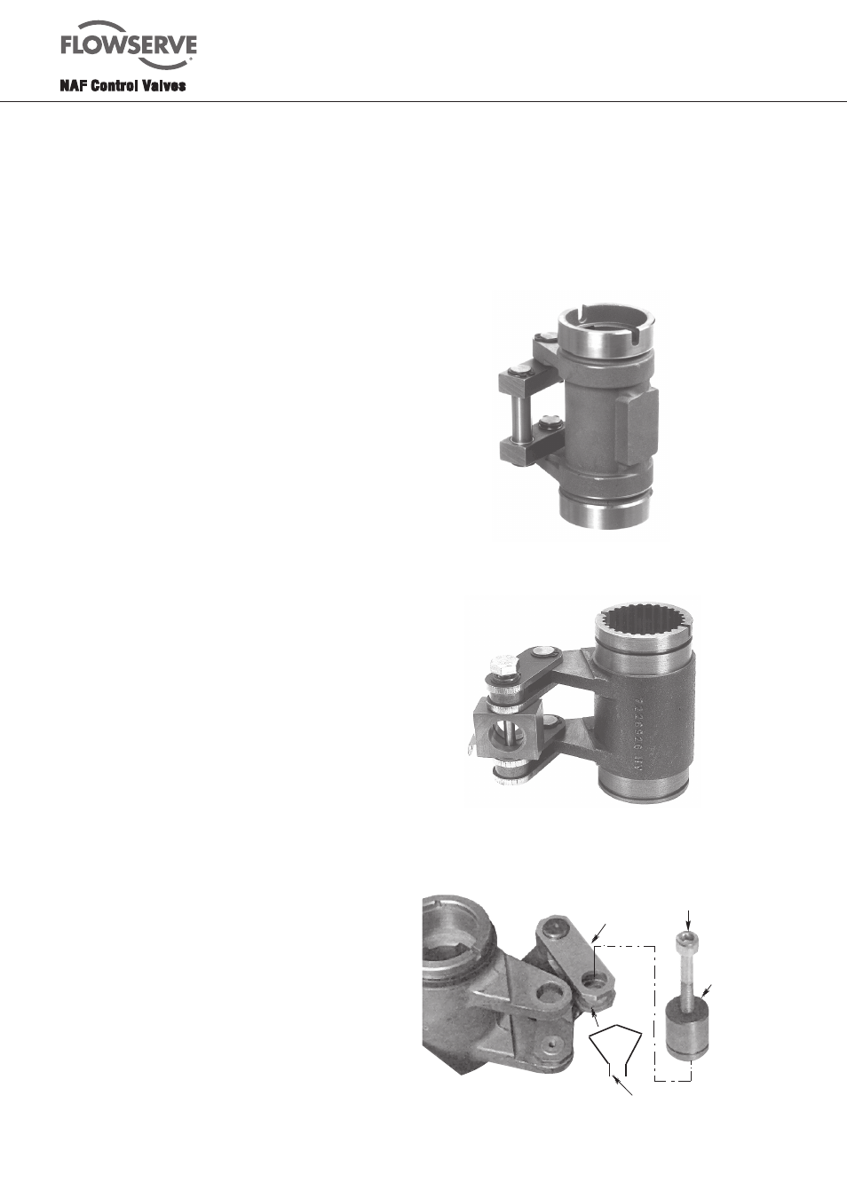
Fig. 1.0. Linkage mechanism, size 0
Fig.1.1. Linkage mechanism, size 1 - 3
Locking clip (10A)
Pin (9)
Link (8)
M5/M8 screw
Fig.1.4. Linkage mechanism, sizes 4 - 5