5 drive sleeve and housing cover disassembly, 6 torque nut disassembly (drive 1 option) – Flowserve L120 Series Limitorque Actuation Systems User Manual
Page 29
29
Limitorque Actuation Systems L120 Series FCD LMENIM1201-04-AQ – 05/15
flowserve.com
6.5 Drive Sleeve and Housing Cover Disassembly
Piece numbers refer to Figure 5.2.
1. Remove Upper Ball Bearing (piece 17), Bevel Gear (piece 18), Declutch Spring (piece 24), Clutch
Sleeve (piece 19), and Key (piece 23).
2. Remove Lower Ball Bearing (piece 16).
3. Spirolox Retainer (piece 22) may now be removed by inserting small flat blade
screwdriver under the end of the ring and prying the first layer from the groove.
Continue around the ring until it is free from the groove.
4. Remove the Worm Gear (piece 21) and the Lug Ring (piece 20).
5. Handwheel Adapter (piece 26) and Seal (piece 42) can be removed from Housing Cover (piece 27)
by removing Retaining Ring (piece 28).
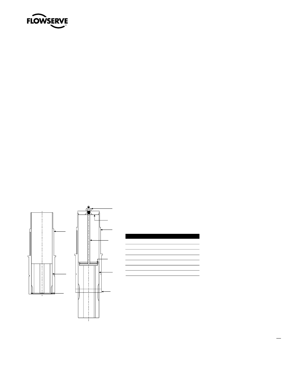
6.6 Torque Nut Disassembly (Drive 1 Option)
For applications requiring torque only, the L120 series actuator can be supplied without the thrust
base option. The torque nut is driven by the drive sleeve lugs and held in place by the torque bushing
connector.
Figure 6.1 – L120-10 through 40 standard and extended drive sleeve assembly
Unless otherwise stated, piece numbers refer to Figure 6.1.
Standard Drive Sleeve
To remove the Torque Nut (piece 95), remove Retaining Ring (piece 183) and drop the torque nut out
the bottom of the Drive Sleeve (piece 25 of Figure 5.2).
25
95
183
25
95
183
97
99
96
98
Extended
Standard
Piece Quantity
Description
25
1
Drive Sleeve
95
1
Torque Nut
96
1
Torque Bushing Connector
97
1
Torque Bushing Washer
98
1
Retaining Ring
99
1
Elastic Stop Nut
183
1
Retaining Ring