Figure 30: mounting interface dimensions – Flowserve LPS Pneumatic Heavy-Duty Actuator Series User Manual
Page 30
LPS Series Heavy-Duty Actuators FCD LFENIM0001-02-AQ – 5/15
30
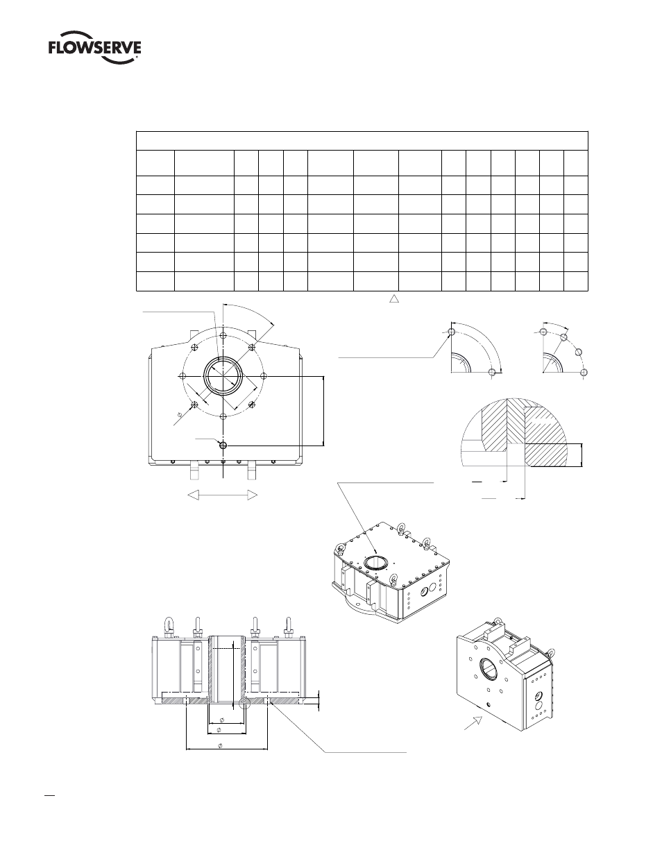
Figure 30: Mounting Interface Dimensions
"U"
IMPORTANT: threaded through
holes. During studs assembly use
Loctite 542 (or equivalent) in order to
obtain a perfect seal.
F
"E"
"G"
"H"
I
L
G H7
H e8
F
E
+
-
0,1
0,1
I
(max keyway length)
IMPORTANT: threaded through
holes. During studs assembly
use Loctite 542 (or equivalent)
in order to obtain a perfect
seal.
Stud threaded length must not
excede "F" + 3 mm.
L
DETAIL W
ØG H7
ØH e8
90°
30°
ATTENTION: The angular positions
of the holes are rotated with respect
to indications of ISO 5211.
The holes are on centerlines.
1
4 Holes Flange
12 Holes Flange
45°
C
"A"
B
n x
"D"
viste da cui sono stati ricavati gli sketches nel disegno
Notes:
- Holes in-line wit axis of actuator (NOt off-center)
- Flange torque different from ISO 5211 specification
ØA D8
C
+
+
0,20
0,10
n x
D
B D10
P ±0,05
G 3/4
45°
IMPORTANT: Position of the
keyways with actuator at 0°
degree (closed position).
Bottom View
(from "U")
W
8 Holes Flange
FLOW LINE
LPS/LHS Series Coupling Dimensions
Model
ISO 5211 Flange
Interface (reference)
ØA
B
C
Number of holes
n
Hole Diameter
ØD
P.C.D.
[mm(inch)]
E
F
ØG
ØH
I
L
P
LPS/LHS 15
F16
65
10
70.6
4
M20
165 (6,50)
18
86
78
161
8
155
LPS/LHS 20
F25
86
12
91.6
8
M16
254 (10)
16
130
112
178
4.5
205
LPS/LHS 25
F30
100
18
108.8
8
M20
298 (11,73)
18
150
133
201
6
230
LPS/LHS 30
F35
130
28
138.6
8
M30
356 (14,02)
28
168
152
261
10
305
LPS/LHS 35
F40
150
36
166.8
8
M36
406 (15,98)
33
199
185
323
9
405
LPS/LHS 40
F48
185
45
205.8
12
M36
483 (19,02)
38
244
230
338
10
450