Worcester actuation systems – Flowserve RT92 Series User Manual
Page 7
7
Resistor
Resistance Value (R8)
Approx. Current Trip Range
A
.75 ohm 5 watt
.8 to 1.6 amp
B
1.5 ohm 5 watt
.4 to .8 amp
C
2.5 ohm 5 watt
.25 to .5 amp
D
.51 ohm 5 watt
1.18 to 2.35 amp
These values were selected to keep the actuator within the
maximum acceptable torque limits.
2. The following table lists the various low power actuator
ordering codes, the motor voltage, and the current sense
resistor to be supplied on the RTU card.
Actuator Code
Supply Voltage
Resistor Code
10 R 75 4-12D
12 volts
B
12 R 75 4-12D
12 volts
B
10 R 75 4-24D
12 volts
C
12 R 75 4-24D
12 volts
C
20 R 75 4-12D
12 volts
A
22 R 75 4-12D
12 volts
A
23 R 75 4-12D
12 volts
D
20 R 75 4-24D
12 volts
B
22 R 75 4-24D
12 volts
B
23 R 75 4-24D
12 volts
A
3. The actuator codes are broken down as follows:
10R75 Single motor
Gearbox mtd. on fast side
4
Duty cycle - 75%
12R75 Single motor
Gearbox mtd. on slow side
20R75 Dual motor
Gearbox mtd. on fast side
12D
Motor voltage - 12 VDC
22R75 Dual motor
Gearbox mtd. on slow side
24D
Motor voltage - 24 VDC
23R75 Dual motor
Gearbox mtd. on slow side
B. Local Operation
The RTU card has been provided with momentary push-button
switches to enable local operation of the actuator for
maintenance, calibration, etc. Depressing switch SW1 will cause
the actuator to operate in the clockwise direction until the switch
is released, an overcurrent condition causes a trip, or the end of
travel limit is reached. Depressing switch SW2 will cause the
actuator to operate in the counterclockwise direction until it is
released, an overcurrent trip occurs, or the end of travel limit is
reached.
C. Remote Operation
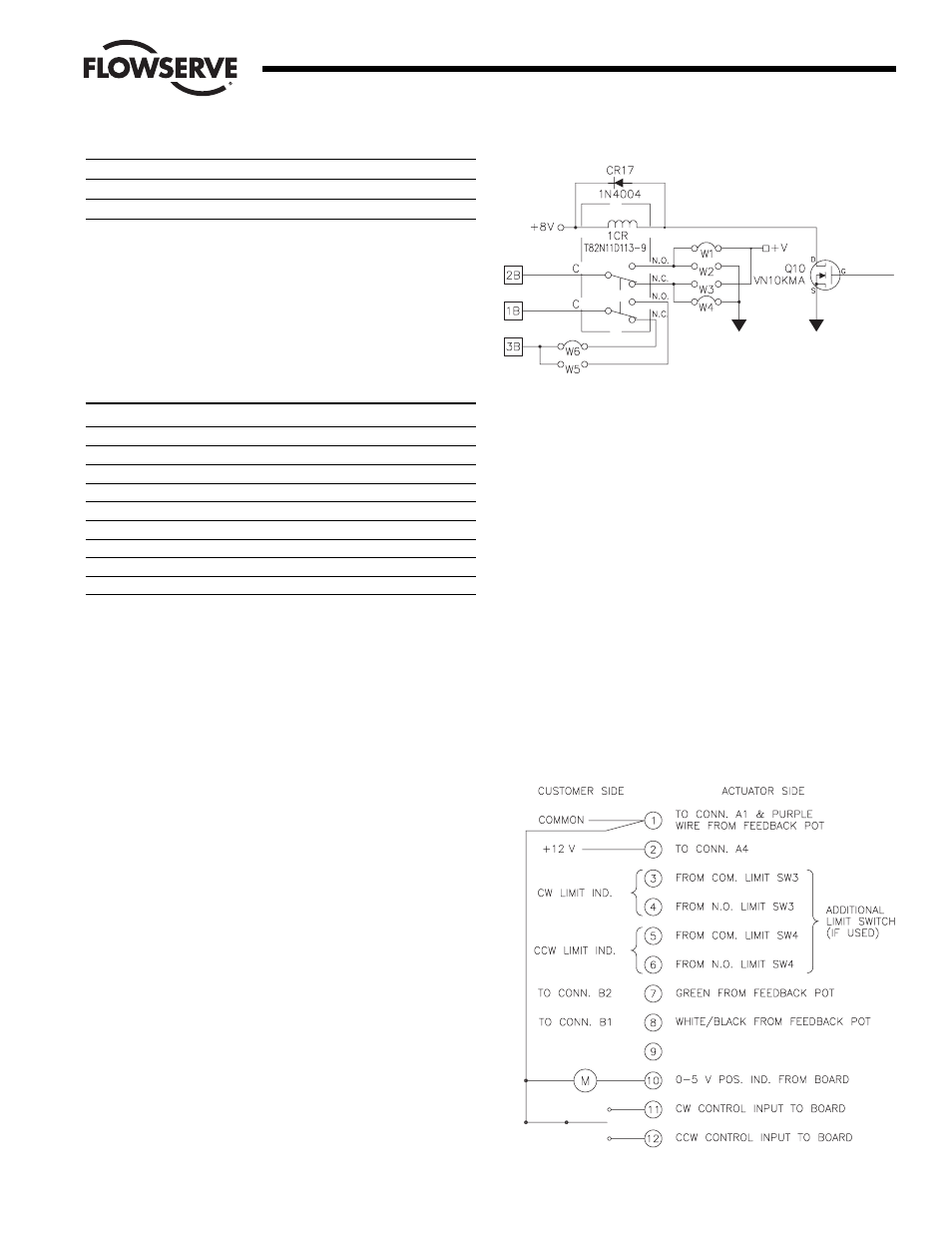
1. Remote operation of the RTU is initiated by bringing terminal
11 for clockwise operation or terminal 12 for
counterclockwise operation to the common/negative voltage
reference level (i.e. same as terminal 1). This will cause the
actuator to operate in the appropriate direction until the signal
is removed, the end of travel limit switch trips, or the unit
trips out on overcurrent. The controller/PLC need only sink
approximately .03 mA in order for the board to operate. In the
event of an overcurrent trip, removal of the control signal and
subsequent reapplication of the signal will reset the trip
circuit. If the cause of the overcurrent condition still exists,
the circuit will again trip.
2. The circuit has also been designed to operate such that the
power can be removed from the board when actuator motion
is not needed. Then when motion is desired, both the power
and the appropriate control signal may be applied at the same
time. This feature can be used when the standby current draw
of the circuit board (about 10 mA) is too much for the solar
power supply when many actuators are involved. Turning
circuit board power on and off along with the control signal
keeps power consumption to an absolute minimum.
D. Fuse Protection
Each of the three circuit board versions has a main power supply
fuse (F1) to protect the power source and circuit board in the
event of a circuit board or motor failure. This fuse is a standard
1.25" 3AG fuse rated at 3 A 250 V. In addition to this fuse, the
Position Output Indication circuit board with the 0-5 volt position
Flow Control
Worcester Actuation Systems
Figure 7
Figure 8