Worcester actuation systems – Flowserve RT92 Series User Manual
Page 4
b. Additional Parts For Version With 0-5 Volt Position
Indication Output:
Qty.
Name
1
Potentiometer Kit Subassembly
2. Tools
Needed:
1
/
4
" nut driver,
1
/
8
" screwdriver, needle nose pliers,
1
/
16
" Allen wrench
(cams and spur gear), volt/Ohmmeter (checking feedback
potentiometer resistance, voltages, incoming control signal).
3. Operational Check of Basic Actuator:
The cams that actuate limit switches 1 and 2 should be set
such that SW-1 trips at the full closed position and SW-2
trips at the full open position.
NOTE:
If extra limit switches are installed for position
indication, their cams should be set to trip the appropriate
extra limit switch 1-2 degrees prior to SW-1 or SW-2 tripping.
If valve torque is not too high, the actuator shaft may be
repositioned manually using the actuator declutch mechanism
to declutch the output shaft and turning the output shaft with
a wrench. If the valve torque is too high, the actuator may be
repositioned electrically by disconnecting connector ‘A’ and
applying the appropriate voltage and polarity to the connector
pins attached to the blue and yellow wires.
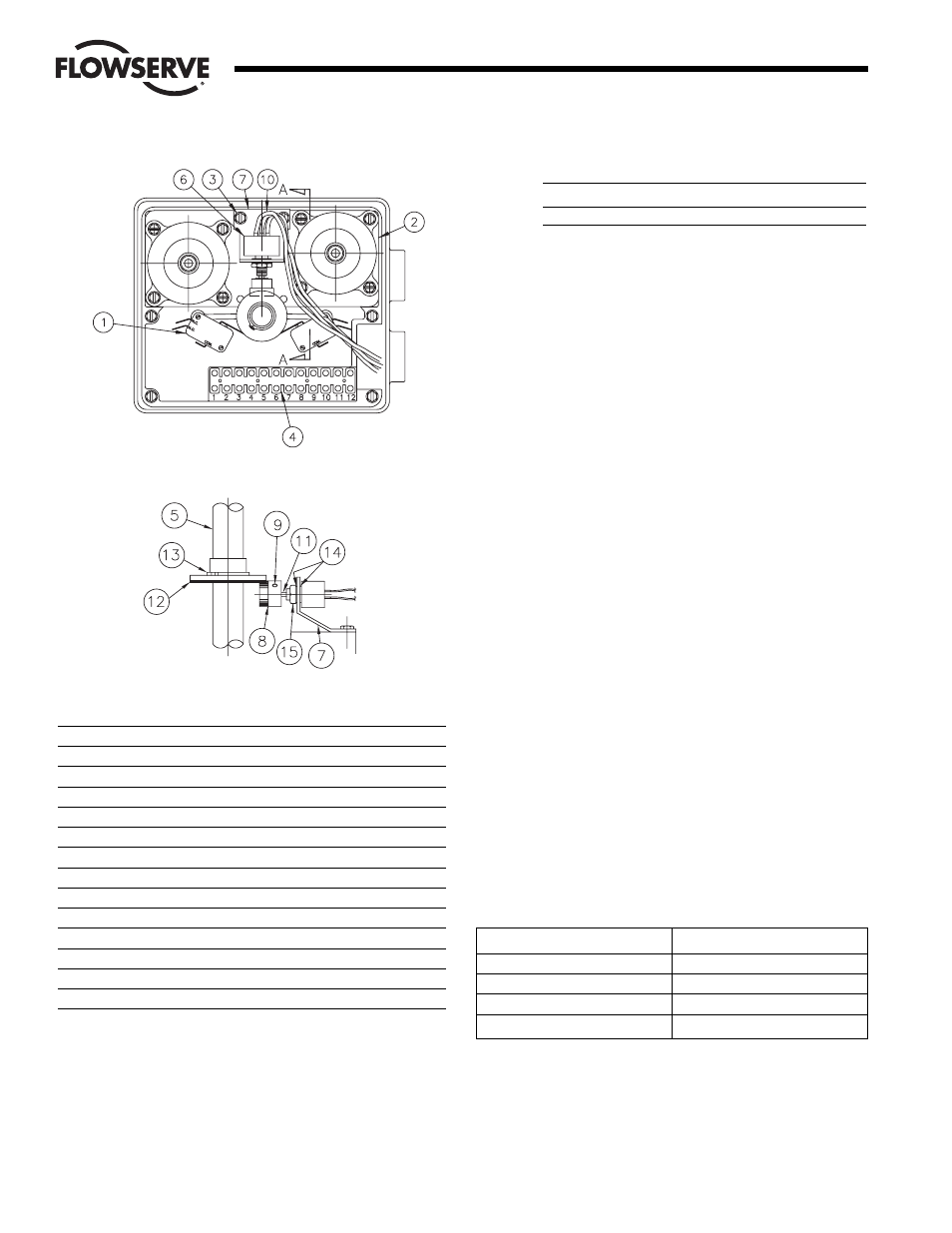
B. Mounting Potentiometer
For Version with 0-5 Volt Output or Where Resistive Position
Feedback is Desired (See Figure 4)
1. Mounting Single Potentiometer Into Series 75 Actuator
With the potentiometer mounted to the potentiometer bracket
and the spur gear loosely fitted to the potentiometer shaft,
mount the potentiometer bracket to the motor module (if not
already mounted) as follows:
Remove the motor module mounting screws on the side of
the module furthest away from the actuator shaft. Position
potentiometer assembly bracket holes over screw holes and
line up potentiometer shaft with center of actuator shaft,
replace and tighten screws.
2. Potentiometer
Wiring:
The feedback potentiometer leads are connected to the
actuator terminal strip as follows:
NOTE:
The feedback pot is wired to the terminal strip for No
Output Indication and Position Output Indication circuit
boards. In the case of the No Output Indication board, the two
wires on the external side of terminal 7 and 8 are removed
and taped with electrical tape. For the Current Trip Indicator
board it will be necessary to hardwire the feedback pot
directly to the customer’s wiring.
4
Flow Control
Worcester Actuation Systems
Figure 4
ITEM
DESCRIPTION
1
Limit Switches
2
Motor Module
3
Motor Module Mounting Screws (2)
4
Terminal Strip
5
Actuator Shaft
6
Potentiometer
7
Potentiometer Bracket
8
Spur Gear
9
Spur Gear Set Screw
10
Potentiometer Leads
11
Potentiometer Shaft
12
Face Gear
13
Snap Ring
14
Lockwashers (2)
15
Nut
For Resistive Position Output
For 0-5 Volt Position Output
Terminal
Wire Color
Terminal
Wire Color
7
Green
1
Purple
8
Wht/Blk
7
Green
9
Purple 8
Wht/Blk
View A-A