Flowserve Automax PMV DS UltraSwitch User Manual
Page 6
11
10
Cam fine adjustment
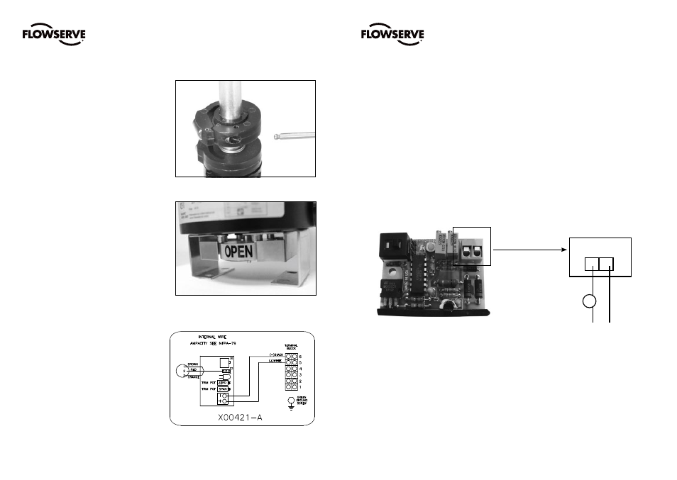
7.3 Cam fine adjustment
Some cams have a fine adjustment available. These
cams will have a small screw embedded into the side
of the cam.
Adjusting this screw clockwise or counter clockwise
will deform the cam, changing the trip point slightly.
7.4 Adjusting Visual Position Indicator
(optional part):
As an option, the DS/DM UltraSwitch™ can be
equipped with a visual indicator located beneath the
housing. This ring-type indicator can easily be adjusted
using manual force. Simply rotate the indicator by hand
to the desired position. Double check that its position
corresponds to the position of the valve.
Mounting instructions are included in the box.
7.6 Calibrating 4-20 mA transmitter
Setting direct/reverse action: A dip-switch setting
controls the direction of increasing travel. For 4 mA in
the full clockwise position, select ”D”, for 4 mA in the
full counterclockwise position, select ”R”.
Adjusting zero/span:
1. Attach a DC mA meter to +/- terminals.
2. Operate valve/switch box to position corresponding
to 4 mA.
3. Adjust feedback board zero trim pot to yield 4
mA. (Turning CW increases value, turning CCW
decreases value).
4. Operate valve/switch box to position corresponding
to 20 mA feedback.
5. Adjust feedback board span trim pot to yield 20
mA. (Turning CW increases value, turning CCW
decreases value).
6. The zero and span adjustments are interactive.
Repeat steps 1 through 5 as necessary.
Note: If transmitter adjustment gets difficult (i.e.,
trim pots do not have desired effect) start again by
”centering” the trim pots. This is accomplished by
turning in one direction for 20 turns and reversing
direction for 10 turns.
7.5 Analog feedback option specifications
Option 4 - 4-20 mA Transmitter
Voltage Supply: 6-30 VAC
Impedance: 300 Ohms at 20 mA
4-20 mA Transmitter
mA meter
6-30 VDC
- +
- +
FCD PMENIM0020-00 - 02/15
FCD PMENIM0020-00 - 02/15