Certificates, Specifications – Flowserve Automax PMV DS UltraSwitch User Manual
Page 3
5
4
5.4 DS/DM UltraSwitch™ nomenclature
4. CERTIFICATES
ATEX II 2 GD Ex d IIC T4 Gb, Ex tb IIIC T113°C Db IP66
IECEx Ex d IIC T4 Gb, Ex tb IIIC T113°C Db IP66
5. SPECIFICATIONS
5.1 Technical data
Enclosure ratings
IP66, IEC 529
Weight Aluminum housing
1.8kg / 4 lbs
Weight Stainless Steel housing
3.5kg / 7.75 lbs
Working Temperature:
-40°C to +85°C / -40°F to +185°F
Maximum Surface Temperature:
+120°C / +248°F
5.2 Materials of construction
Housings & Covers
Powder epoxy painted Aluminum or Stainless Steel
Shaft
Stainless
Steel
Cams/Splines
Nylon
Terminal
Block
Nylon
Internal Brackets
Nylon, Aluminum or Stainless Steel
All External Fasteners
Stainless Steel
All Internal Fasteners
Stainless Steel
Indicator
Polycarbonate/Polyurethane
Label
Polyester or Stainless Steel
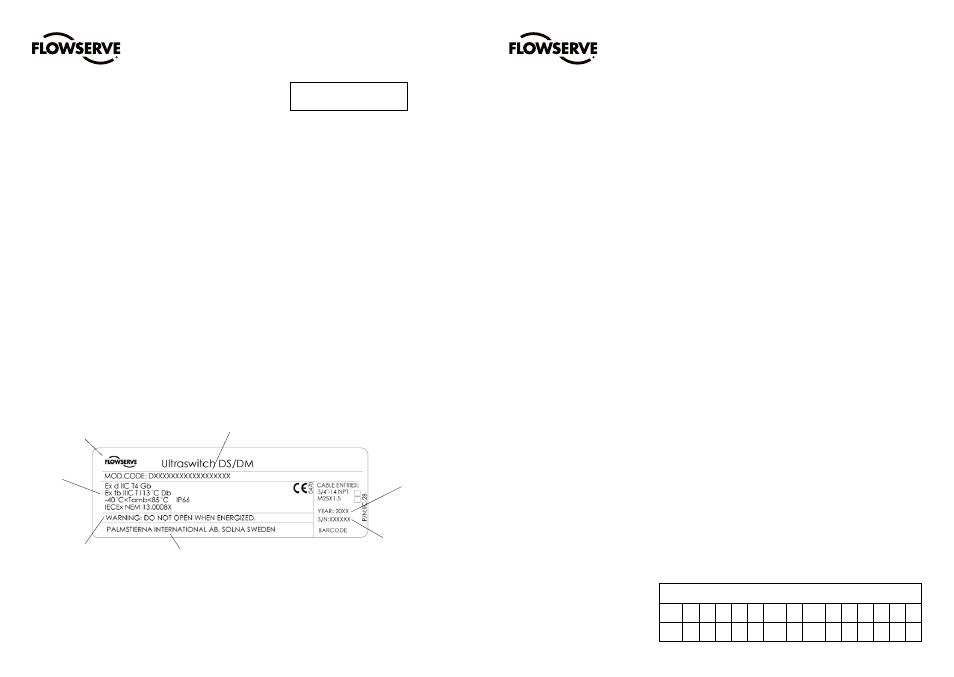
Product name and model code
Warnings
Year of
manufacture
Manufacturer
Electrical
rating
Serial number
Logotype
5.3 Product label
All certificates available for
download at www.pmv.nu
FCD PMENIM0020-00 - 02/15
FCD PMENIM0020-00 - 02/15
A =
Product & Connections (cable entry)
DS
Explosion proof / Flame proof switch box with 3/4” NPT cable entries
DM
Explosion proof / Flame proof switch box with M25x1,5 cable entries
B =
Number of open cable entries
2
2 x open cable entries (standard)
3
3 x open cable entries (option)
C =
Housing material /Surface treatment
B
Aluminum housing, polyester powdercoating, Black base & cover
W
Aluminum housing, polyester powdercoating, Black base & White cover
C
Aluminum housing, polyester powdercoating, Black base & Optional cover color
S
Stainless Steel housing DIN 1.4408 - EN G-X 6 CrNiMo 18-10 - SAE 316
D =
Shaft
D
Double ’D’ Shaft 1/4”
N
Namur VDI/VDE 3845 Shaft (rotary actuators)
T
For NAF Turnex actuators
L
D style including nut for linear applications
E =
Indicator option
0
Flat top cover, no indicator
1
Flat top cover, indicator below switchbox for 90 deg
F =
Qty of switches
0
0 switches (Cam assembly for 2 x M1 only)
2
2 Switches
4
4 Switches
G =
Switch options - see page 6 for switch options
H =
Certificate
14
General Purpose
19
ATEX II 2 GD Ex d IIC, IECEx Ex d IIC
I =
Product approval marking
0
Self-adhesive marking label, Polyester
M
Stainless steel marking plate
J =
Analog Output
0 None
4
4-20mA transmitter
(F=0 only)
K =
Terminal Options
2
2 Extra open terminals (Standard)
4
4 Extra open terminals (Optional, not possible for all switch options)
6
6 Extra open terminals (Optional, not possible for all switch options)
8
8 Extra open terminals (Optional, not possible for all switch options)
H
Heavy Duty Terminal Block, 8 contact points.
L =
Options/ Elastomers
0
Nitrile O-rings
V
Viton O-rings
M =
Brand
P PMV
Ordering code example
A
B C D E F
G
H
I
J K L M
DS 2 B N 1 2 MG - 14 - 0 0 2 0 P