Flowserve ZK210 User Manual
Page 11
11
Explanatory Notes
(continued)
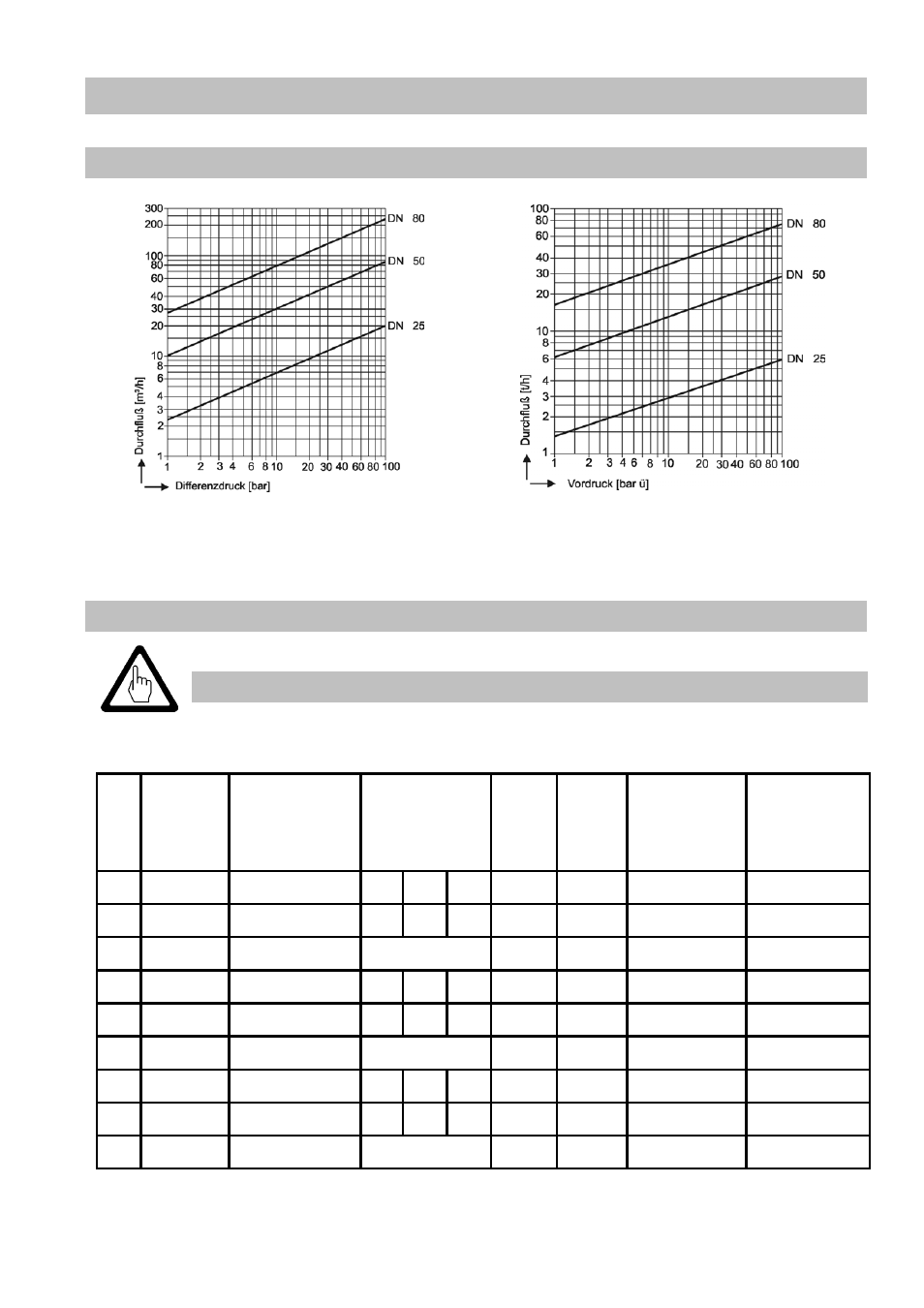
Capacity Charts
Cold water
Hot water t
s
–5 K
The charts show the maximum flowrates of cold and hot water at the extreme regulation
position with linear characteristic curves and maximum K
vs
value.
K
vs
Values and Actuator Selection Data
Important
In the installation instructions, standard values are described. For possible
deviations, please see the name plate of the control valve.
DN Nozzle
*)
Characteristic K
vs
value
[m3/h]
Valve
lift
[mm]
Revol.
for full
valve
lift
Max. admiss.
torque for
opening/
closing
[Nm].
Type/size of
actuator
DIN ISO
5210
25
3-stage linear
0.8 1.5 2.3
18
3.6
20 / 20
F10 - B1
25
3-stage equal %
0.8 1.5 2.3
18
3.6
20 / 20
F10 - B1
25
4-stage linear
0.5
13
2.6
20 / 20
F10 - B1
50
3-stage linear
3.3 6.5 10
35
7
30 / 60
F10 - B1
50
3-stage equal %
3
6
9
35
7
30 / 60
F10 - B1
50
5-stage linear
2
23
4.6
30 / 60
F10 - B1
80
3-stage linear
9.5 18
28
50
10
80 / 120
F10 - B1
80
3-stage equal %
8.5 18
25
50
10
80 / 120
F10 - B1
80
5-stage linear
5
35
7
80 / 120
F10 - B1
*) 3-stage:
∆p
max
= 100 bar (standard), 4/5-stage:
∆p
max
= 180 bar