Basic setting – Flowserve NRGT26-1 User Manual
Page 17
7
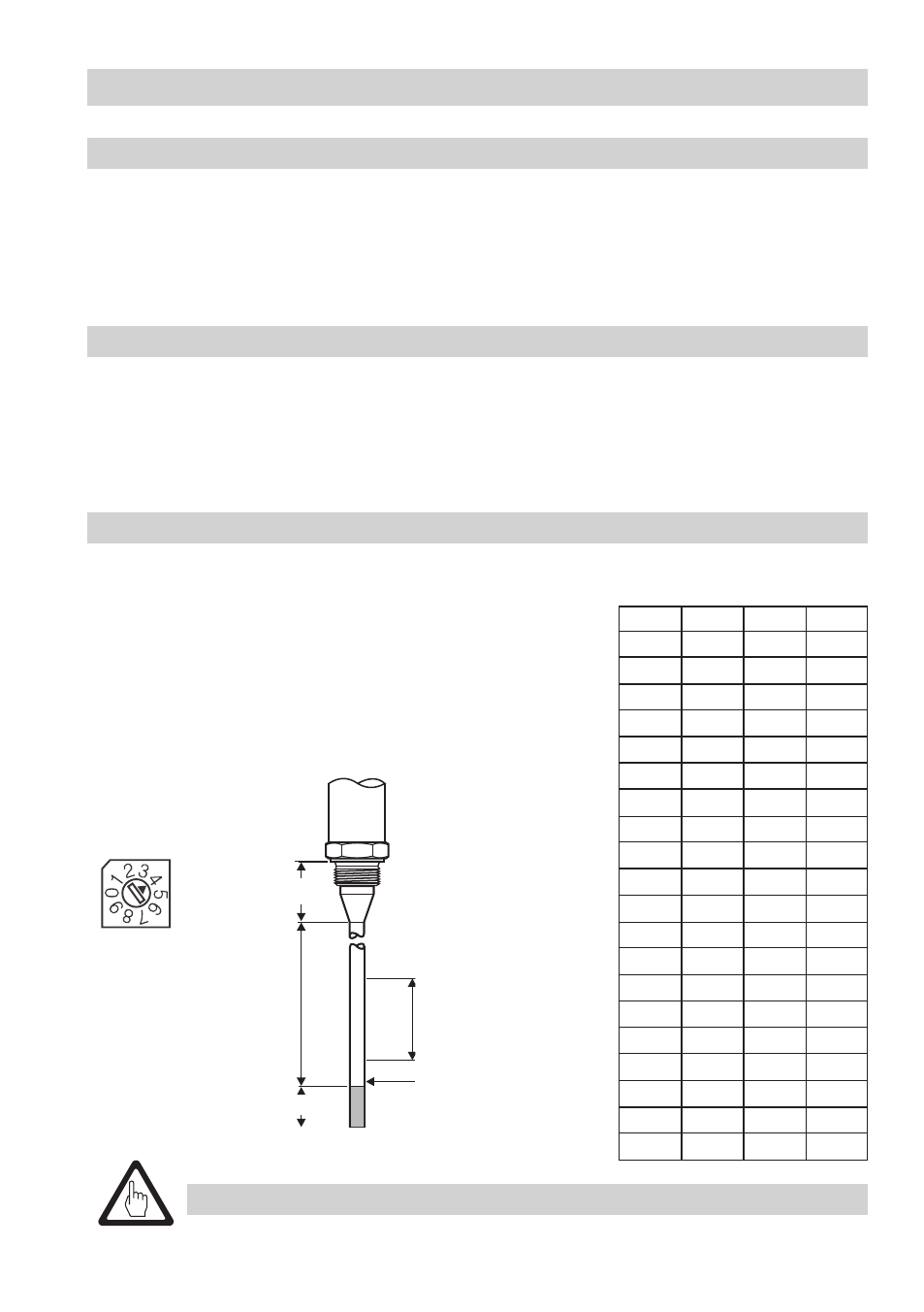
Basic Setting
Factory setting NRGT 261
The compact system is delivered with the following factory set default values:
■
Measuring range
300 mm:
Switch
K position 4, water ≥ 20 µS/cm
■
Measuring range
400 mm up to
700 mm: Switch
K position 4, water ≥ 20 µS/cm
■
Measuring range
800 mm up to 500 mm: Switch
K position 4, water ≥ 20 µS/cm
■
Measuring range 600 mm up to 2000 mm: Switch
K position 5, water ≥ 20 µS/cm
X Control range [mm] (active measuring range)
2 Max. measuring range at 25 °C
5 Water, conductivity ≥ 20 µS/cm
6 Water, conductivity ≥
2
5 µS/cm
7 Fuel oil EL, dielectric constant ε
r
2.3
4
4
4
4
4
4
4
4
4
4
4
4
4
4
4
5
5
5
5
5
00
200
300
400
500
600
700
800
900
000
00
200
300
400
500
600
700
800
900
2000
3
3
3
4
4
4
4
4
5
5
5
5
5
5
5
5
6
6
6
6
3
3
3
3
3
3
3
3
3
3
3
3
3
3
3
3
3
4
4
4
Lower measuring
point
26
Attention
■
If
X is clearly smaller than 2 set switch K one step back.
Establish active measuring range (control range)
A control range may be established within the measuring range of the electrode. Establish the length
of the control range using switch
K, see Fig. 8
Factory setting NRGT 261S
The compact system is delivered with the following factory set default values:
■
Measuring range
275 mm:
Switch
K position 4, water ≥ 20 µS/cm
■
Measuring range
375 mm up to
675 mm: Switch
K position 4, water ≥ 20 µS/cm
■
Measuring range
775 mm up to 475 mm: Switch
K position 4, water ≥ 20 µS/cm
■
Measuring range 575 mm up to 975 mm: Switch
K position 5, water ≥ 20 µS/cm
Fig. 14
37
X
5
6
7
X
2
K