Wiring – Flowserve NRGT26-1 User Manual
Page 16
6
Wiring
Use multi-core flexible control cable with min. conductor size .5 mm
2
for wiring.
.
Undo screws
H
, remove housing cover
J. Fig. 7
2. Unscrew union nuts of cable entry
I.
The electrode terminal can be turned through +/– 180 °.
3. Loosen plug
U with 7 mm spanner but do not remove. Fig. 8
4. Turn electrode terminal into desired direction (+/– 80 °).
5. Tighten plug
U slightly.
6. Remove terminal strips
S from board.
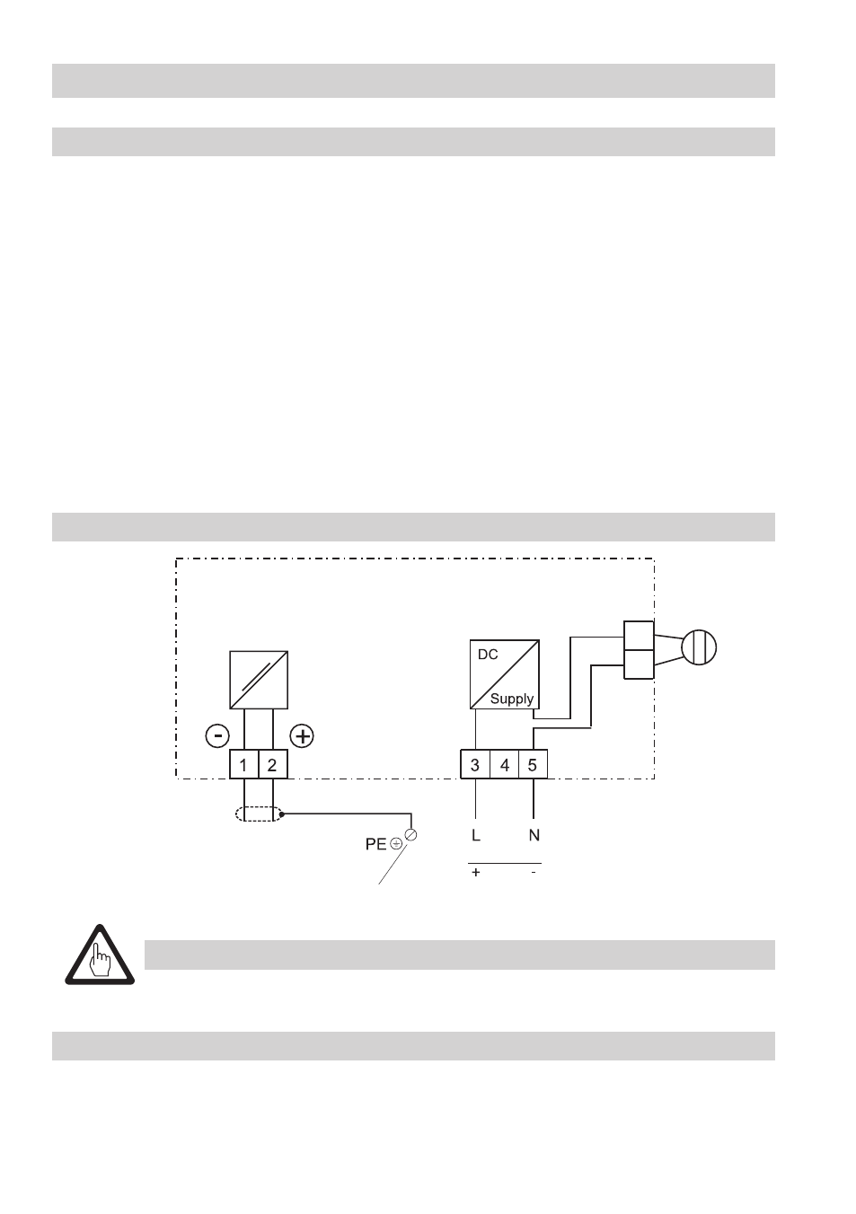
7. Connect terminal strip according to wiring diagram, connect PE connection
T.
8. Plug in terminal strips
S.
9. Install cable entry
I.
0. Replace housing cover
J, insert screws H and fasten.
NRGT 261, NRGT 261S
■
Fuse supply cables with 250 mA (slow blow).
Tools
Attention
Wiring diagram
■
Screwdriver for cross head screws, size
■
Screwdriver for slotted screws, size 2.5; completely insulated according to DIN VDE 0680-
■
Open-end spanner 7 mm A. F.
Fig. 13
Thermal fuse
Mains
24 V DC
4-20 mA
Max. load
500
Ω
Earthing screw
in enclosure
NRGT 261
NRGT 261S