Flowserve 191400 Series User Manual
Page 6
6
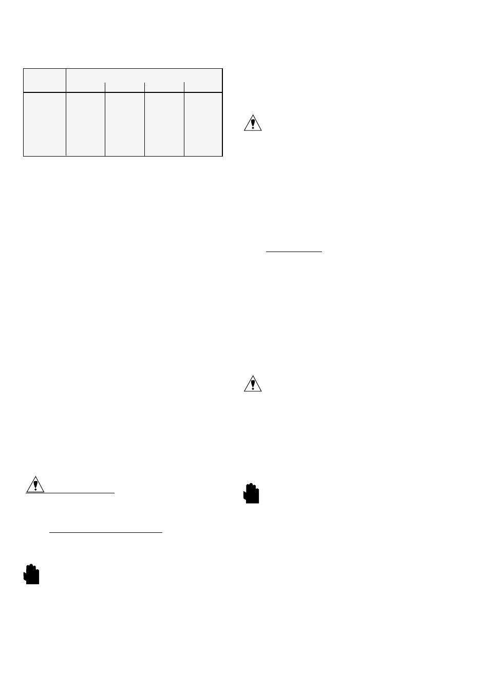
5.4.4 Welding fillers
Filler match-up table
Material to
Suitable welding filler
be welded
1.4316
1.4430
1.4440
1.4519
1.4301
x
1.4306
x
1.4401
x
1.4404
x
1.4435
x
x
x
1.4571
x
x
5.4.5 Final treatment of weld
Interior area
Final treatment of weld not required. Surface quality
can be improved at accessible points by grinding.
Exterior areas
Final treatment process:
Pickling– brushing– grinding- polishing
5.5
Cleaning
Clean entire valve thoroughly before installing.
5.6
Installation
Install according to installation instructions.
6
DISASSEMBLY AND ASSEMBLY
(see fig. 2)
6.1
Installation
To remove the complete valve, separable connections
must be provided in the vicinity of the valve connec-
tions a and b.
We recommend following distances from the valve:
Product inlet (a) : 1 x diameter
Product outlet (b) : 6 x diameter
7
DISASSEMBLY
Please observe separate documentation for disas-
sembly of the actuator.
CAUTION:
Before disassembly:
depressurise the line to atmospheric pressure and
drain all fluid from the valve, close-off the supply air.
Valves with air-to-open actuators: tension the actua-
tor springs using top handwheel or by applying sup-
ply air under the membrane.
WARNING: Failure to do this will cause the valve bon-
net to spring-out when the clamp is released due to
the spring pressure acting between the plug and seat.
Observe electrical connection voltage, as necessary
switch off power supply.
7.1
Disconnect pneumatic and electrical feed lines.
7.2
On air-to-open / spring-to-close actuators tension
actuator springs.
7.3
Remove actuator
Remove the coupling between the actuator stem and
the plug stem (3). Loosen the slotted nut (M38x1.5)
on the valve bonnet (2) and remove the actuator.
7.4
Release the tension on actuator springs.
7.5
Loosen and remove the TC clamp (4).
7.6
Remove the bonnet assy (2) from the body (1).
CAUTION: To avoid damage to the O-ring (6) do not
turn the bonnet.
7.7
Pull the plug/stem (3) out of the bonnet (2).
7.8
Carefully remove the wiper (5).
7.9
Remove the O-Ring (7) which serves as the stem seal.
7.10 Remove the body O-Ring (6)
7.11 Remove the PTFE-guide (8) from the bonnet (2).
8
ASSEMBLY
Please observe separate documentation for assembly
of the actuator.
Before assembly:
Thoroughly clean all surfaces.
8.1
Place O-Ring (7) in the bonnet (2).
8.2
Place the wiper (5) in the bonnet (2).
8.3
Place the housing gasket O-Ring (6) in the shoulder
provided on the bonnet (2).
8.4
Insert the PTFE-guide (8) carefully in the bonnet (2)
and ensure it is seated correctly to prevent damage to
the guide.
8.5
Insert the plug/stem (3) into the bonnet (2) .
8.6
Place the bonnet assy. (2) on the body (1).
CAUTION: Insert the body straight. Ensure that the
O-Ring (6) is seated correctly in the groove in the bon-
net. To avoid damage to the O-ring (6) do not rotate
the bonnet.
8.7
Ensure that the bonnet is seated correctly on the body
without a gap between the two. Replace the TC clamp
(3) and tighten securely.
8.8
On air-to-open /spring-to-close apply supply pressure
to move actuator to half stroke.
WARNING: If the actuator is not moved to half stroke
the plug can contact the body when assembling and
damage the seating faces and/or the valve body.
8.9
Mount the actuator on the valve and secure with slot-
ted nut (M38x1,5).
8.10 Attach the coupling between valve and actuator.
8.11 Release tension on the actuator springs.
8.12 Reconnect pneumatic and electrical feed lines and
prepare the valve for cleaning.
STOP!
STOP!