Flowserve 191400 Series User Manual
Page 5
5
4
SAFETY
The valves described in this documentation are de-
signed and produced so that they do not present any
hazard for the operating and service personnel or for
the system, in which the valves are installed, when
handled properly observing all important instructions
and safety precautions.
All installation and removal work, performed within the
scope of maintenance or repair to the valves, should
be accomplished only by trained personnel. When
assembling or disassembling, observe the installation
instructions. Proceed precisely as specified in the in-
stallation and removal instructions to prevent severe
injury to the operating and service personnel.
The operator of the system is responsible for ensur-
ing that the installation, operating and maintenance
personnel assigned have the required qualifications.
The operator is also responsible for ensuring that the
personnel in question are familiar with the documenta-
tion and safety regulations.
The values listed in the chapter “Technical Data”, such
as pressure, temperature, installation locations, etc.,
should be observed under all circumstances.
All materials and sealing elements must be suitable for
these operating conditions and the media, with which
the valves come into contact. The system operator
is solely responsible for all risks and consequences
resulting from failure to observe these operating
parameters. Unauthorized modifications to the valves
have an effect on the intended application and are not
permissible.
In addition to these instructions, all local safety and
accident prevention regulations apply.
5
INSTALLATION
5.1
General Instructions
We urgently recommend having the installation
work accomplished by trained, expert personnel.
5.2
Delivery Status
The valves are tested at the factory and ready for in-
stallation when shipped. The valve can be connected
to the product line with weld ends or selected pipe
connections.
5.3
Installation Guidelines
5.3.1 Installation Space
Before starting installation determine and define the
connection axes. Take installation dimensions from
dimension drawings. Provide for space for operation
as well as service.
5.3.2 Installation
Do not subject to pressure or tension.
5.3.3 Installation Position
Vertical, to ensure that valve and line run empty.
5.4
Welding Guidelines
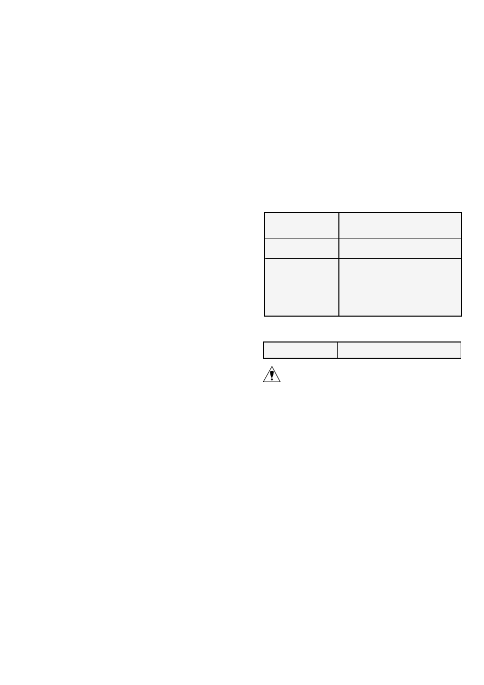
Range of application Welding between weld connections
and piping acc. to DIN 11850 Series 2
Welding procedure
TIG (tungsten Inert gas welding)
Type of weld
• Prepare weld acc to DIN 2559
(joint shape I / for I-welds)
• Welds conforming to EN 25817
⇒ evaluation group B (high)
butt weld I-joint acc. to DIN 8532
5.4.1 Welding in valves
Installation state
Single-piece body
CAUTION: To prevent damage to sealing materials and
functioning parts, always weld the body in a disas-
sembled state. Disassemble according to disassemble
instructions.
5.4.2 Preparation of weld
Cut off ends of pipe even and deburr. Adjust weld-
ing ends on housing so that they make radially and
axially level contact with the piping (centering tool).
Ensure that no gap is present at the welding ends
in contact with each other, because otherwise the
forming gas would flow out reducing the corrosion
resistance of the weld.
5.4.3 Welding
Connect forming gas. Tack 3-4 points. TIG welding,
manual or orbital (machine welding).