Worcester controls – Flowserve 51 Series Fire-Safe Valves User Manual
Page 11
19406-H
11
Flow Control Division
Worcester Controls
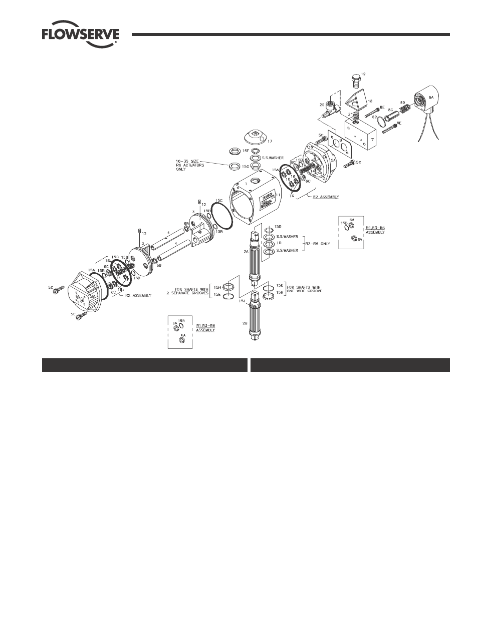
1
1
Body
2A
1
Shaft (10-2039)
2B
1
Shaft (25-3539)
3
2
Pistons
4
2
Guide Rods
5A
1
Solenoid Block (Inlet) End Cap
5B
1
Limit Switch End Cap
5C
8
End Cap Screws (Metric)
*6
Bearings (Guide Rod)
6A
4
End Cap Bearing (Split Ring Style)
6B
2
Piston Bearing (Split Ring Style)
6C
4
End Cap Bearing (Top Hat Style)
7
1
Solenoid Block (Spring Return)
8A
1
Solenoid
8B
1
Solenoid O-Ring
8C
1
Solenoid Plunger
8D
1
Solenoid Spring
8E
2
Solenoid Block Bolts
9
1
Solenoid Block Gasket
10
1
Thrust bearing (Available in R6 RK only)
11
1
Nameplate
12
2
Piston Set Screws
13
2
Pipe Plugs
14
6
Springs (R2-R6)
14
16
Springs (R1)
15
REBUILDING KIT (Includes the following)
15A
2
End Cap O-Rings
15B 6 or 12
Guide Rod O-Rings (See Note)
15C
2
Piston O-Rings
15D
1
Top Shaft O-Ring
15E
1
Bottom Shaft O-Ring
15F
1
Shaft Clip
15G
1
Top Pinion Bearing
15H
1
Bottom Pinion Bearing
15J
1
Anti-Ejection Ring (R1 & Sizes 25-35 R3-R6)
16
4 or 8
Bearing Retainer (R2 Only)
17
1
Position Indicator
18
1
Splash Guard
19
1
Fusible Plug
20
1
Tee Fitting
21
1
Guard Spring
ITEM
QTY
DESCRIPTION
ITEM
QTY
DESCRIPTION
Actuator Exploded View