Flowserve Valtek MaxFlo 3 User Manual
Page 10
®
User instructions - MaxFlo 3 - VLENIM0052-02 02.07
0
9
ACTUATOR REMOUNTING
NOTE: The MaxFlo 3 valve opens in a clockwise direc-
tion when looking down the valve shaft.
9.
When remounting the actuator to the valve, refer to the
appropriate actuator manual.
NOTE: The actuator stroke stops must be adjusted cor-
rectly to avoid any over-rotation of the plug stroke. Poor
adjustment can cause damage to the valve. Pay special
attention to the adjustment of the closing stop when the
valve has a soft seat.
9.
Install the valve in the pipeline as indicated in the “Instal-
lation” section according to the orientation recommen-
dations given at the end of the manual.
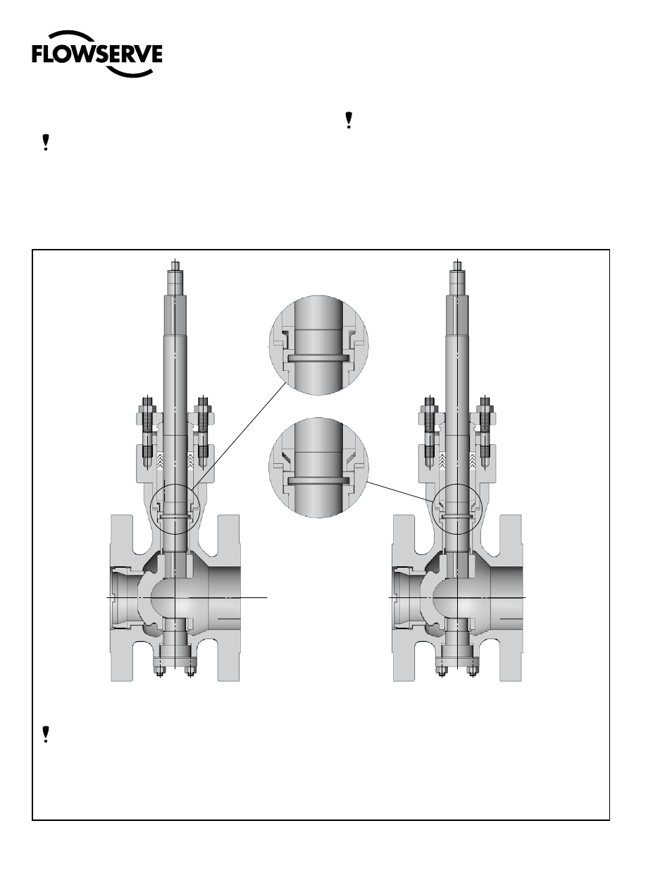
Figure 6a: old design
It is possible to upgrade from the old design (prior to
mid-2006) by changing the bonnet (40) and the pack-
ing stop (99).
To order the correct replacement parts, contact your
Flowserve representative with the serial numbers of
the valves requiring the upgrade.
10. PRINCIPLES OF SHAFT ANTI-BLOWOUT SYSTEM
Figure 6b: new design
NOTE: The MaxFlo 3 valve has been significantly im-
proved, with even greater safety for the anti-blowout
system.
The diameter of the shaft shoulder exceeds the diam-
eter of the bonnet bore. Even if the thrust bearing (item
46) is not installed during reassembly, the shaft can-
not pass through the bonnet.