Flowserve SB Control Valves User Manual
Page 7
3
2
11
ShearStream SB
FCD VLENIM4152-01 07.09
7
10. Fitting the Actuator to the Valve
1. The actuator can be mounted directly on the
valve. The mounting fl ange and the valve stem
follow the NAF standard for securing the
actuator.
2. Turn the valve to the closed position. The key
should face towards the inlet.
3. Fit the actuator.
4. Connect the compressed air supply to the
actuator - applies to pneumatic actuators. If the
end position stop is correctly set, the ball
segment will not move when compressed air
pressure is applied.
5. If moving - adjust the end position stop until the
actuator has turned the ball segment to the
closed position.
6. General
The actuator may be fi tted either in line with the
connected pipes or transversely to them. An
intermediate plate is necessary for mounting the
actuator in line with the pipework.
N.B. The direction of closure must always be
clockwise, as viewed from the actuator.
Before fi tting the actuator, it is important to ensure that
the actuator fi ts the stem. First try without key to check
that the drive slips onto the shaft. Also check that the
key fi ts and matches the keyways in the shaft. Grease the
actuator shaft entry. Push the actuator onto the stem.
The travel of the ball sector should be restricted to 90°,
which is the travel necessary between fully open and
fully closed. If the sector is turned beyond this range,
the sealing surfaces of the sector and seat ring may
be damaged when an attempt is made to turn the
ball sector back to the correct position and the sector
may jam against the seat ring.
In practice, this is prevented by the indicating pin which
will come into contact with the bolts retaining the top
cover if an attempt is made to turn the ball sector outside
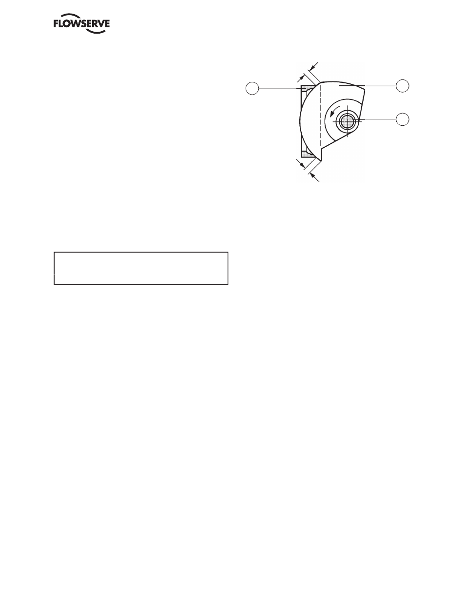
the range between fully open and fully closed. When
adjusting the actuator, make sure that, in the closed posi-
tion, the sphere of the ball sector (2) is located opposite
the seat ring (11), i.e. that the sphere projects beyond the
seat ring by equal amounts on each side of the seat as
shown in Fig. 5.
clockwise, as viewed from the actuator.
Fig. 5. Locating of the ball sector sphere when
adjusting the actuator