Flowserve Valtek FlowTop General Service Control Valve User Manual
Page 4
60-4
Flowserve Corporation, Valtek Control Products, Tel. USA 801 489 8611
Lapping the seat (not required)
Lapping the seat is not required for class 4
shut off.
1. The plug and seat sealing surfaces can be improved
by lapping, using a good quality carborundum paste
with 280 grit size. Type
2-F-Crystolon lapping
compound has a proven suitability and can be
purchased from US Products, 518 Melwood Avenue,
Pittsburgh, PA, 15213 PH: 412 621 2130.
2. Apply lapping compound to seating surfaces of plug
and seat ring. For smaller trims, only apply lapping
compound to the seat (0.39-inches and smaller).
3. Prior to lapping the plug into the seat ring, assemble
the body sub-assembly. Torque the bonnet nuts (114)
to the specified values from Table II. Install the stem
guide (82), packing (88) and packing follower (83) to
support the plug stem when lapping the plug and seat.
It is not required to install the bonnet gasket (55) for
lapping procedure. Lapping tools are available if
needed. The plug and seat can be lapped by replacing
the packing with a lapping bushing (See Table V for
wrench and bushing part numbers.)
4. Lap the plug into the seat ring (Figure 3) to obtain
good seating surfaces on both. Grind the seating
surfaces by applying moderate axial pressure on
the plug stem. Avoid a full 360 degree rotation. Best
results will be achieved by a limited rotation, back
and forth, approximately 60 degrees. Do not remove
too much metal; stop the lapping after seating
surfaces of 0.031-inch (0.8 mm) wide has been
obtained in seating of plug. Ensure plug is seated
completely. Lapping the seat usually only takes a
few minutes, provided the seating surface is free of
damage and the seat ring is fully round. After
lapping is complete, keep the plug and the seat in
the same contact orientation; this ensures better
shut-off.
5. After lapping is complete, it is recommended to
clean the lapping compound off the trim. Prior to
disassembly, ‘match mark’ the plug (50), bonnet (40)
and body (1). After cleaning the lapping compound
from the trim, rebuild the valve aligning the match
marks of the body, bonnet and plug stem, ensure
bonnet gasket (55) is installed.
WARNING: Do not scratch or score the plug
stem.
Replacing plug
1. On fail-closed actuators, the preadjusted spring
force is effective. Therefore, apply enough air
pressure to the actuator to stroke the stem to mid-
stroke (50 percent stroke) before disconnecting
actuator and valve stem.
2. Remove the bonnet nuts (114).
3. Lift off the bonnet (40), actuator and plug (50) as
an assembly.
4. Disconnect actuator stem (211) and plug stem (50)
by removing the stem clamp bolting (345 and 240)
and the stem clamp (249).
5. Loosen the packing box gland nuts (117) until
finger-tight.
6. Remove the plug (50) from the bonnet (40). A
replacement plug may now be fitted if required.
When withdrawing or replacing the valve stem use
a gentle turning motion to avoid damage to the
packing material.
NOTE: The plug and packing should be replaced
at the same time. (See Packing Replacement.)
Replacing seat ring
1. Remove the actuator, bonnet (40) and plug (50) from
the valve body. (See
Replacing Plug Procedure
steps 1-5.)
2. Replace the seat ring using a suitable seat-ring tool
(Figure 2). Seat removal tools can be purchased
from Flowserve if required. (See Table III.)
3. Apply high-performance lubricant to the threads on
the seat ring. When refitting the seat ring, Mo S
2
additives are also advantageous if compatible with
the process fluid.
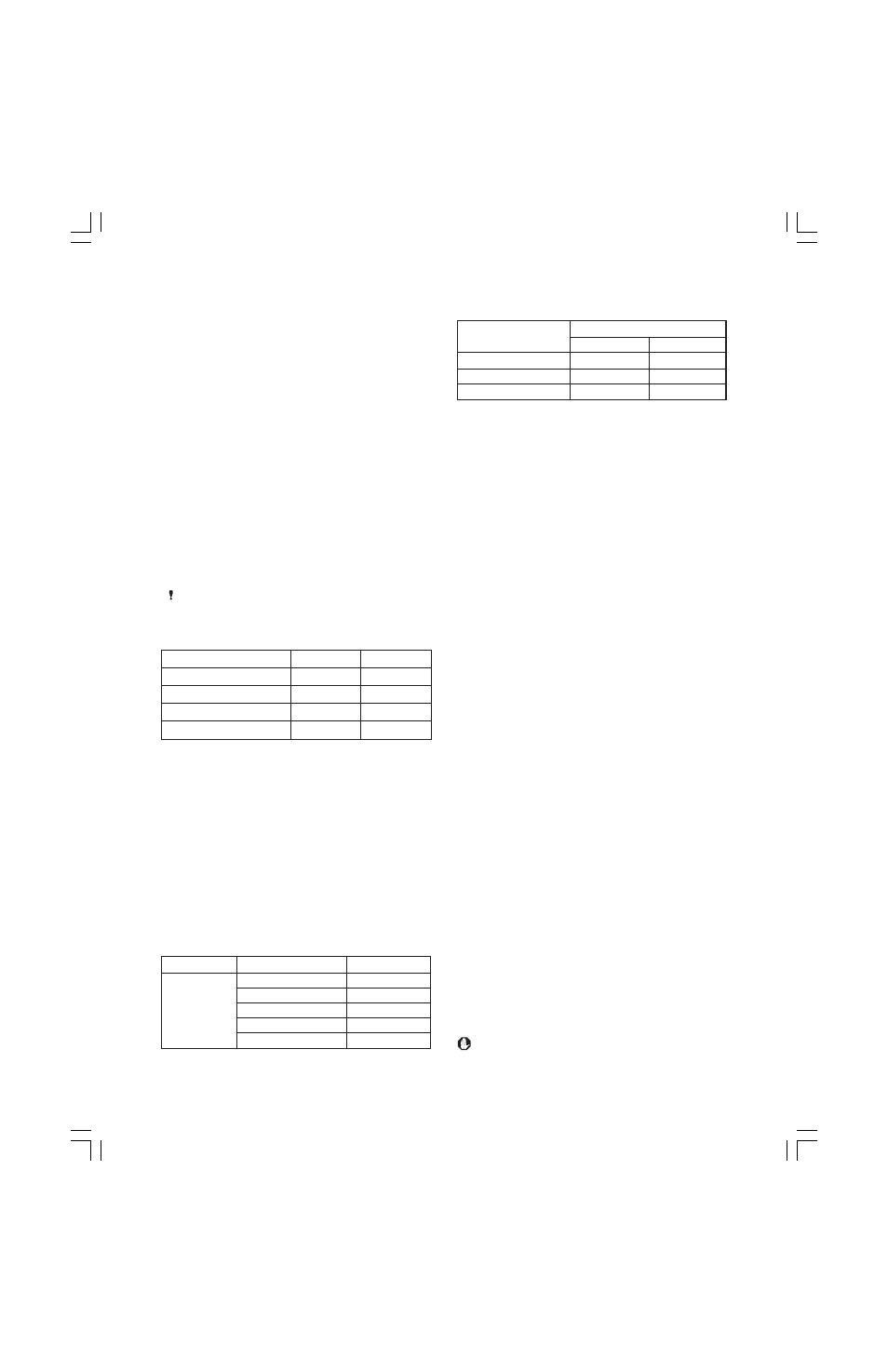
Model
psi
bar
19 in
2
(127 cm
2
)
90
6
39 in
2
(252 cm
2
)
90
6
78 in
2
(502 cm
2
)
90
6
109 in
2
(700 cm
2
)
90
6
Table III: Maximum Supply Pressure
Table IV: Seat Removal Tools
Item
SIZE (inches)
Part No.
1/2-1
93979
Seat
1.5
93981
Tools
2
93982
3
93976
4
93978
e
z
i
s
e
v
l
a
V
)
s
e
h
c
n
i
(
e
u
q
r
o
T
s
b
l
-
t
f
m
N
2
,
5
.
1
,
1
,
5
7
.
0
0
5
1
0
0
2
3
5
2
2
5
0
3
4
0
0
3
0
0
4
Table V: Seat Ring Torque
IM049 FlowTop IOM.p65
2/10/03, 12:34 PM
4