Flowserve Valtek FlowTop General Service Control Valve User Manual
Page 15
Flowserve Corporation, Valtek Control Products, Tel. USA 801 489 8611
60-15
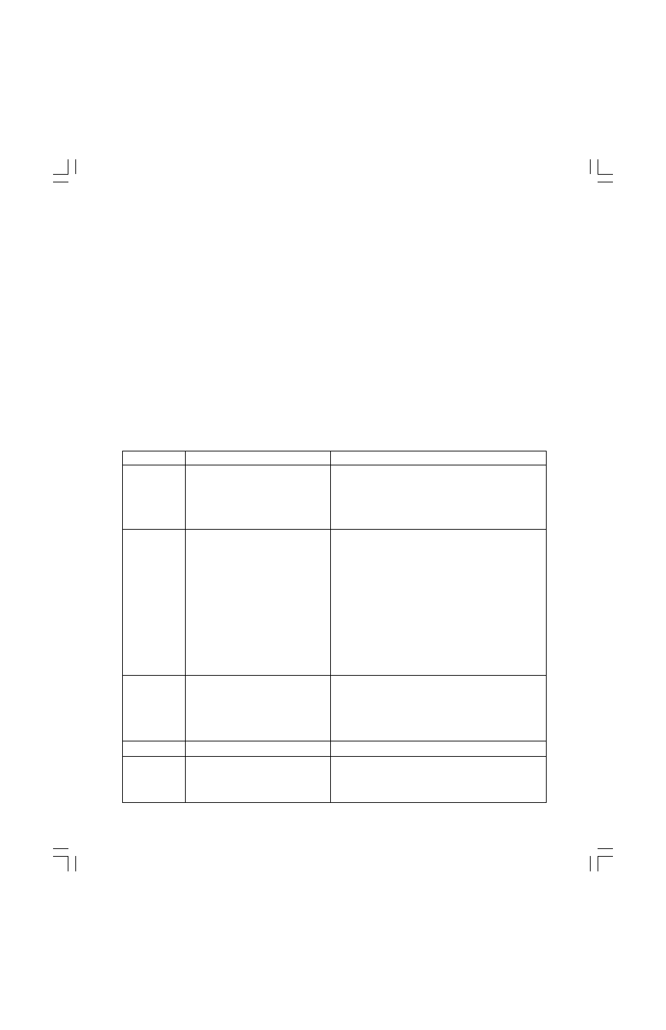
Troubleshooting FlowTop Control Valves
Problem
Probable Cause
Corrective Action
Stem motion
1. Overtightened packing
1. Adjust packing box nuts to slightly over finger-tight
impeded
2. Service temperature is beyond
2. Reconfirm service conditions and contact factory
operating limits of trim design
3. Inadequate air supply
3. Check for leaks in air supply or instrument signal
system; tighten loose connections and replace
leaky lines, verify spring set values
Excessive
1. Malfunctioning positioner
1. Refer to positioner maintenance instruction manual
leakage
2. Improperly tightened bonnet
2. Refer to
Preventive Maintenance and Table II
flange bolting
section for correct tightening procedure
3. Worn or damaged seat ring
3. Disassemble valve and replace or repair seat ring,
follow proceedure in
Replacing Plug and Seat
4. Inadequate actuator thrust
4. Check for adequate air supply to actuator; verify
spring set values; if air supply is adequate,
reconfirm service conditions and contact factory
5. Incorrectly adjusted plug
5. Refer to
Stroke Length Adjustment for correct plug
adjustment
6. Incorrectly adjusted zero
6. Recalibrate positioner (see Step 1)
adjustment locknut
7. Improper handwheel adjustment
7. Adjust handwheel until plug seats properly
acting as a limitstop
Inadequate
1. Improper plug adjustment,
1. Refer to
Stroke Length Adjustment for correct
flow
limiting stroke
plug adjustment
2. Malfunctioning positioner
2. Refer to positioner maintenance IOM
3. Service conditions exceed trim
3. Verify service conditions and consult factory
design capacity
4. Insufficient air supply pressure
4. Verify air supply requirements, spring set values
Plug slams
1. Incorrect flow direction
1. Install valve in flow-under direction
Valve does
1. Incorrect flow direction
1. Reconfirm direction and, if necessary, correct flow
not fail in
direction through valve
correct
2. Wrong failure direction
2. Reverse spring failure direction on actuator; refer
position
to
Reversing the Actuator Action
Air Supply Connection
For actuators without positioners, control air is con-
nected directly to the air supply port of the appropriate
actuator housing: for direct-acting actuators (air-to-
close / fail-open) to the upper housing and for reverse-
acting actuators (air-to-open / fail-close) to the lower
actuator housing. The air connections for tandem ac-
tuators are illustrated in Figure 12.
For actuators with positioners, the air piping is factory
installed depending on the required action direction. In
the field, only the air supply needs to be connected to
the positioner or to the air filter regulator.
The threads of the actuator supply ports are 0.25-inch
NPT. Other air connections are available on request.
IM049 FlowTop IOM.p65
2/10/03, 12:34 PM
15