Fig. 2: anti-rotation device – Flowserve 2 Series P5 Type User Manual
Page 7
7
Flow Control Division
Kammer Control Valves
8.1.2
Actuator action spring-to-open
8.1.2.1 As required remove the actuator from the valve as described
in section 1.1.
8.1.2.2 Remove all case retaining screws (20).
8.1.2.3 Remove the upper case half (22).
8.1.2.4 With a suitable press compress the spring set.
8.1.2.5 Secure the actuator stem (34) against rotating with a wrench
across the flats on the stem’s lower part and remove the lock
nuts (24).
8.1.2.6 Remove following parts:
washer (1), diaphragm (31), piston (29), spring plate (28),
spring set (37), spring plate (27), plate (26) and spacer
(25).
8.1.2.7 Disassemble the lower actuator as described in sections
8.1.2.2 to 8.1.2.6.
8.1.2.8 With a hooked spanner loosen and remove the slotted nut
(9).
8.1.2.9 Remove the guide (4) and upper yoke plate (8).
8.2
ASSEMBLE ACTUATOR
(refer to Figs. 1 and 2)
8.2.1
Actuator action spring-to-close
8.2.1.1 Insert the guide (4) into the lower body half.
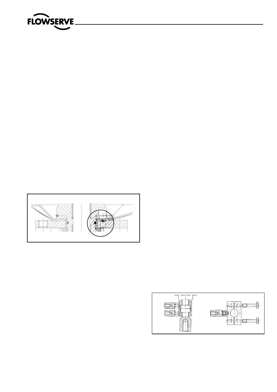
8.2.1.2 Replace the upper yoke plate ensuring that the nose in the
lower body rests in the bore of the upper yoke plate (see
fig. 2).
8.2.1.3 Refit the slotted nut (9) and tighten with a hooked spanner.
8.2.1.4 Refit the actuator stem (10), washer (1), diaphragm (31),
piston (29), spring plate (28), spring set (37), spring plate
(27), plate (26) and spacer (25)
8.2.1.5 Secure the actuator stem (10) from rotating with a wrench
across the flats on the stem’s lower part and torque the nut
(24) to 35 Nm. Replace and tighten actuator stem (34) and
secure with loctite 221.
8.2.1.6 Replace the upper case half.
8.2.1.7 Insert 4 x 100 mm long (de)compression screws (21) through
the upper and lower actuator case halves and tighten with
long nuts (31) in equal measures until the casing halves
contact.
8.2.1.8 Insert and tighten all remaining short case retaining screws
(20) to a torque value of 12 Nm.
8.2.1.9 Assemble the upper actuator as described in sections
8.2.1.4 to 8.2.1.8.
8.2.1.10 Secure the actuator stem (34) from rotating with a wrench
across the flats on the stem’s lower part and torque the nut
(24) to 35 Nm. Replace locknut (24) and secure with loctite
221.
8.2.1.11 Replace the upper case half.
8.2.1.12 Insert and tighten the upper case retaining screws (20) in
equal measures to a torque value of 12 Nm.
8.2.1.13 As required refit the actuator assembly to the valve as
described in section 1.2.
8.2.2
Actuator action spring-to-close
8.2.2.1 Insert the guide (4) into the lower body half.
8.2.2.2 Replace the upper yoke plate ensuring that the nose in the
lower body rests in the bore of the upper yoke plate (see
fig. 2).
8.2.2.3 Refit the slotted nut (9) and tighten with a hooked span-
ner.
8.2.2.4 Refit the actuator stem (10), spacer (25), plate (26),
spring plate (27), spring set (37), spring plate (28), piston
(29), diaphragm (29) and washer (1).
8.2.2.5 With a suitable press compress the spring set.
8.2.2.6 Secure the actuator stem (10) from rotating with a wrench
across the flats on the stem’s lower part and torque the nut
(24) to 35 Nm. Replace and tighten actuator stem (34) and
secure with loctite 221.
8.2.2.7 Release the press and replace the upper case half.
8.2.2.8 Insert and tighten the case retaining screws (20) in equal
measures to a torque value of 12 Nm.
8.2.2.9 Assemble the upper actuator as described in sections
8.2.2.4 to 8.2.2.8.
8.2.2.10 Secure the actuator stem (34) from rotating with a wrench
across the flats on the stem’s lower part and torque the nut
(24) to 35 Nm. Replace and tighten locknut (24) and secure
with loctite 221.
8.2.2.11 Release the press and replace the upper case half.
8.2.2.12 Insert and tighten the case retaining screws (20) in equal
measures to a torque value of 12 Nm.
8.2.2.13 As required refit the actuator assembly to the valve as
described in section 1.2.
Fig. 2: Anti-rotation device
8.3
NAMUR ACCESSORIES
(see Fig. 3)
8.3.1 Accessories according to NAMUR can be fitted by
flanging them to the yoke. A special coupling half with
threaded bosses is available to connect the actuating
lever (see spare parts list for part-no.).
Fig. 3: NAMUR coupling half