Flowserve 2 Series P5 Type User Manual
Page 5
5
Flow Control Division
Kammer Control Valves
1
A 30 00 90 05
Washer
2
A AG 01 25 ID
Bushing
3
A AG 00 25 UL
O-Ring 22 x 2
4
A 30 00 80 00
Guide
5
A AG 00 35 NB
O-Ring 32,99 x 2,62
6
A 60 00 30 01
Lower body
7
A 60 00 50 01
Flange
8
A PS 03 28 05
Yoke plate
9
0 10 03 89 A2
Nut M 38 x 1,5
10
A 60 01 35 05
Actuator stem
11
A PS 03 70 05
Yoke rod
12
A AG 05 10 81
Coupling half.
13
A AG 05 30 A2
Screw
14
A AG 05 70 05
Coupling insert
15
0 10 03 36 A2
Nut, M10
16
A PS 01 02 05
Yoke plate
17
0 10 00 34 A2
Washer, Ø 6,4
18
0 10 03 34 A2
Nut, M 6
19
0 36 01 80 00
Travel indicator, assy.
20
0 10 02 24 A2
Screw M 6 x 30
21
0 10 02 31 A2
Screw M 6 x 110
22
A 60 00 20 01
Upper body
23
0 36 06 00 PA
Vent plug
24
0 10 00 69 A2
Nut, M 16
25
A 60 01 02 AP
Spacer
26
A 60 00 75 01
Plate
27
A 60 00 70 01
Spring plate
28
A 60 00 71 01
Spring plate
29
A 60 00 60 01
Piston
30
A AG 06 03 Al E
Sticker
31
A 60 00 10 EC
Diaphragm
32
A 60 00 86 71
Nut M 6 x 95
33
A 60 00 98 05
Guide
34
A 60 01 51 05
Actuator stem
35
A 60 00 94 05
Spacer ring
36
A 60 00 95 05
Intermediate ring
37*
–
Spring set
* Do not change the spring set thrust or increase the air
supply pressure without first consulting the manufacturer.
Service to the actuator is best performed when the actuator is removed from the valve body. For the purpose of these instructions, consider the
actuator as a separate subassembly with the procedures described in these instructions being performed on a bench. However, many service
repairs and adjustments can be accomplished in the field while the actuator and valve body are still connected to each other.
6
REMOVING AND INSTALL ACTUATOR
6.1
REMOVING ACTUATOR
(refer to Fig. 1)
6.1.1
Shut off air supply.
WARNING: Depressurise the line to atmospheric pressure
and drain all fluids from the valve before working on the
actuator. Failure to do so can cause serious injury.
6.1.2
Disconnect all tubing.
6.1.3
Remove 2 screws (13) and remove coupling (12).
6.1.4
Remove yoke rod retaining nuts (15) and lift actuator
assembly from the valve.
6.1.5
Remove coupling insert (14) and it’s locknut from plug
stem.
NOTE: Ensure that the plug assembly is not rotated with
the plug seated. This may cause irreparable damage to the
seating faces.
6.2
INSTALL ACTUATOR
(refer to Fig. 1)
The actuator stem must be fully extended:
Actuators with air-to-open action must be fully vented.
Actuators with air-to-close action apply supply pressure.
Manually depress the plug stem to ensure the plug is fully
seated.
6.2.1
Screw coupling insert locknut and coupling insert as far as
possible onto plug stem.
6.2.2
Place the actuator assembly on the valve engaging the yoke
rod threads in the lower yoke plate and ensuring the actuator
faces in the correct direction.
6.2.3
Unscrew the coupling insert until the yoke rods are raised
from the lower yoke plate by around 2 mm.
NOTE: Ensure that the plug assembly is not rotated with
the plug seated. This may cause irreparable damage to the
seating faces.
6.2.4
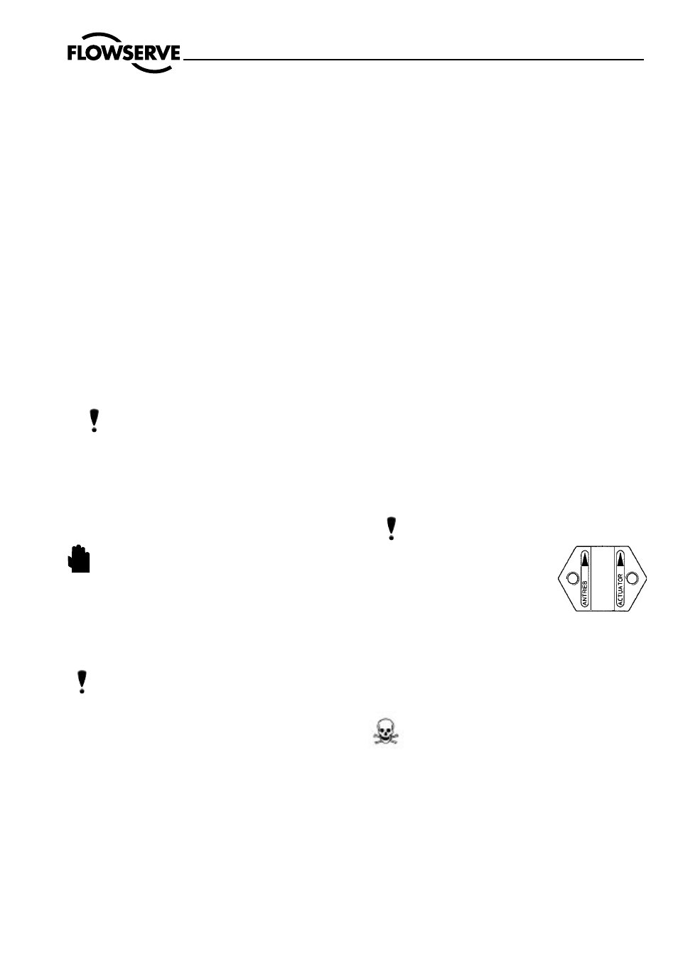
Refit the coupling (12), ensuring
that the arrows, embossed on the
coupling halves, point upward
towards the actuator, and secure with
2 retaining screws (13).
6.2.5
Apply supply pressure resp. vent actuator to half stroke and
refit and tighten yoke rod retaining nuts (15).
6.2.6
Connect all tubing.
7
REVERSE THE ACTUATOR ACTION
(refer Fig. 1)
DANGER: Actuators with “spring-to-close” action
can be disassembled and reassembled by using long
(de)compression screws. A suitable press is required to
disassembled and reassemble actuators with “spring-to-
open” action or to reverse the actuator action.
7.1
Reverse actuator action from spring-to-close to spring-
to-open
7.1.1
As required remove the actuator from the valve as described
in section 1.1.
7.1.2
If long (de)compression screws are not already fitted to the
actuator: remove 4 equally spaced case retaining screws
(20).
STOP!
NOTE: The trim is a very vunerable. Great care must be taken to prevent
damage to the pug and seat facings.
The upper yoke plate (8) and the yoke rods (11) are always removed and replaced with the actuator.