Wiring diagram for can bus, Wiring, Fig. 6 – Flowserve LRR1-40 TDS Control Unit User Manual
Page 17
17
– con tinued –
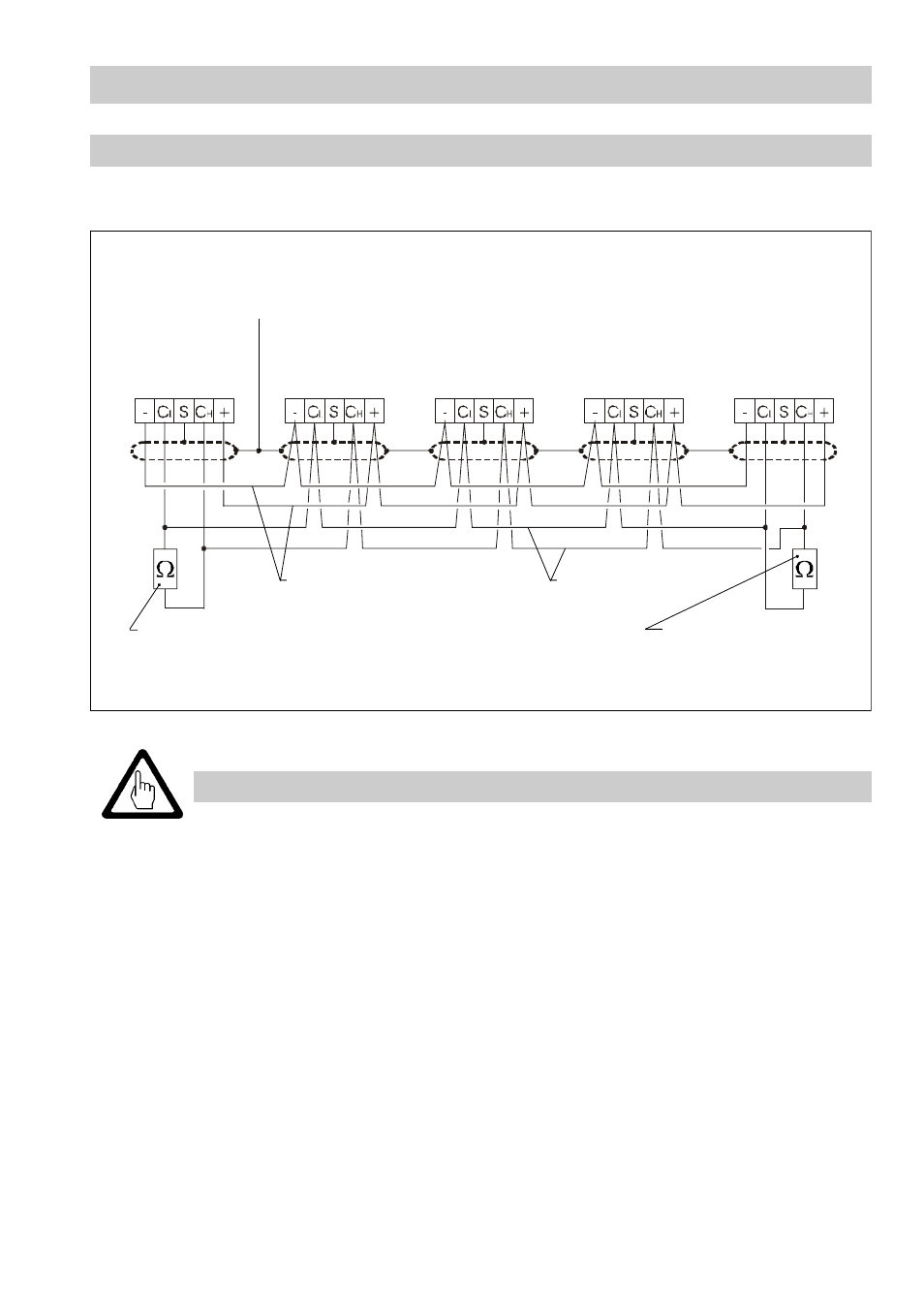
Wiring diagram for CAN bus
The following wiring diagram serves as an example:
Central
earthing point
CEP
Operating
device URB
Control unit
...
Conductivity
electrode
LRG 16- 40
Level
electrode
NRG ...
Terminating resistor
120
Ω
Terminating resistor
120
Ω
Voltage supply
CAN data line
Control unit
LRR 1-40
Fig. 6
Attention
■
Wire equipment in series. Star-type wiring is not permitted!
■
Link screens of bus cables such that electrical continuity is ensured and
connect them
once
to the central earthing point (CEP).
■
To protect the switching contacts provide the circuit with a T 2.5 A or 1A
fuse ( TRD 604, 72 hours operation without constant supervision ).
■
If two or more system components are connected in a CAN bus system,
provide the first and the last device with a terminating resistor of 120
Ω
(terminal CL/CH Fig. 6).
■
The CAN bus system must not be interrupted during operation.
In the event of an interruption a malfunction alarm is raised.
If the control unit has to be replaced, detach the terminal strip (Fig. 2).
Before taking the CAN bus line from the terminal strip, make sure that all
connected system components are out of service.